

Pre-Phase A Report - Lisa - Nasa
Pre-Phase A Report - Lisa - Nasa
Pre-Phase A Report - Lisa - Nasa

Create successful ePaper yourself
Turn your PDF publications into a flip-book with our unique Google optimized e-Paper software.
144 Chapter 7 Spacecraft Design<br />
Radiator<br />
Plate<br />
Solar<br />
Arrays<br />
Y-shaped<br />
Payload<br />
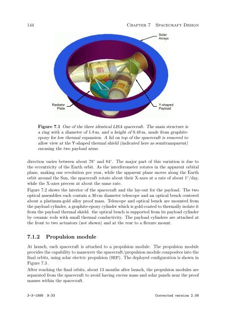
Figure 7.1 One of the three identical LISA spacecraft. The main structure is<br />
aringwithadiameterof1.8 m, and a height of 0.48 m, made from graphiteepoxy<br />
for low thermal expansion. A lid on top of the spacecraft is removed to<br />
allow view at the Y-shaped thermal shield (indicated here as semitransparent)<br />
encasing the two payload arms.<br />
direction varies between about 78 ◦ and 84 ◦ . The major part of this variation is due to<br />
the eccentricity of the Earth orbit. As the interferometer rotates in the apparent orbital<br />
plane, making one revolution per year, while the apparent plane moves along the Earth<br />
orbit around the Sun, the spacecraft rotate about their X-axes at a rate of about 1 ◦ /day,<br />
while the X-axes precess at about the same rate.<br />
Figure 7.2 shows the interior of the spacecraft and the lay-out for the payload. The two<br />
optical assemblies each contain a 30 cm diameter telescope and an optical bench centered<br />
about a platinum-gold alloy proof mass. Telescope and optical bench are mounted from<br />
the payload cylinder, a graphite-epoxy cylinder which is gold-coated to thermally isolate it<br />
from the payload thermal shield. the optical bench is supported from its payload cylinder<br />
by ceramic rods with small thermal conductivity. The payload cylinders are attached at<br />
the front to two actuators (not shown) and at the rear to a flexure mount.<br />
7.1.2 Propulsion module<br />
At launch, each spacecraft is attached to a propulsion module. The propulsion module<br />
provides the capability to maneuver the spacecraft/propulsion module composites into the<br />
final orbits, using solar electric propulsion (SEP). The deployed configuration is shown in<br />
Figure 7.3 .<br />
After reaching the final orbits, about 13 months after launch, the propulsion modules are<br />
separated from the spacecraft to avoid having excess mass and solar panels near the proof<br />
masses within the spacecraft.<br />
3-3-1999 9:33 Corrected version 2.08