

Pre-Phase A Report - Lisa - Nasa
Pre-Phase A Report - Lisa - Nasa
Pre-Phase A Report - Lisa - Nasa

Create successful ePaper yourself
Turn your PDF publications into a flip-book with our unique Google optimized e-Paper software.
44 Chapter 2 Different Ways of Detecting Gravitational Waves<br />
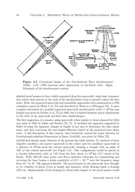
Figure 2.3 Conceptual design of the Gravitational Wave Interferometer<br />
(GWI). Left: GWI structure after deployment in low-Earth orbit. Right:<br />
Schematic of the interferometer system.<br />
shielded proof masses in three widely separated drag-free spacecraft, using laser transponders<br />
rather than mirrors at the ends of the interferometer arms to greatly reduce the shot<br />
noise. Both, the separated spacecraft and monolithic approaches were mentioned in a 1976<br />
committee report by Weiss et al. [73] and described by Weiss in a 1979 paper [74]. A more<br />
complete discussion of a possible separated spacecraft interferometer with 1×10⁶ km arm<br />
lengths was given by Decher et al. [75] in 1980, but it required frequent major adjustments<br />
to the orbit of one spacecraft and had other disadvantages.<br />
The first suggestion of a mission using spacecraft orbits similar to those planned for LISA<br />
was made in 1981 by Faller and Bender [76, 77]. It included the appraoch suggested by<br />
Faller of using the apparent changes in length of one arm to determine the laser phase<br />
noise, and then correcting the arm length difference based on the measured laser phase<br />
noise. A full description of this concept, then tentatively named the Laser Antenna for<br />
Gravitational-radiation Observation in Space (LAGOS), was given by Faller [78].<br />
LAGOS had already many elements of the present-day LISA mission. It consisted of three<br />
drag-free satellites, one master spacecraft in the center and two auxilliary spacecraft at<br />
adistanceof106km from the central spacecraft, forming a triangle with an angle of<br />
120◦ at the central spacecraft (see Figure 2.4). This configuration would be placed in<br />
a circular heliocentric orbit at 1 AU from the Sun, about 4×10⁷ km (15◦ ) ahead of the<br />
Earth. With 100 mW laser power and 50 cm diameter telescopes for transmitting and<br />
receiving the laser beams a strain sensitivity of δl/l =10−19 over the frequency range<br />
from 10−4 to 10−1 Hz appeared feasible. The proof masses in the spacecraft were thought<br />
to be cylinders of about 15 cm in length and diameter, freely floating inside a housing<br />
of 25 cm. Displacements of the housing by 10 µm with respect to the proof masses would<br />
3-3-1999 9:33 Corrected version 2.08