

Pre-Phase A Report - Lisa - Nasa
Pre-Phase A Report - Lisa - Nasa
Pre-Phase A Report - Lisa - Nasa

Create successful ePaper yourself
Turn your PDF publications into a flip-book with our unique Google optimized e-Paper software.
2.8 The LISA concept 49<br />
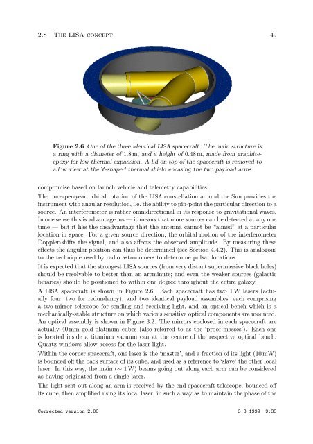
Figure 2.6 One of the three identical LISA spacecraft. The main structure is<br />
aringwithadiameterof1.8 m, and a height of 0.48 m, made from graphiteepoxy<br />
for low thermal expansion. A lid on top of the spacecraft is removed to<br />
allow view at the Y-shaped thermal shield encasing the two payload arms.<br />
compromise based on launch vehicle and telemetry capabilities.<br />
The once-per-year orbital rotation of the LISA constellation around the Sun provides the<br />
instrument with angular resolution, i.e. the ability to pin-point the particular direction to a<br />
source. An interferometer is rather omnidirectional in its response to gravitational waves.<br />
In one sense this is advantageous — it means that more sources can be detected at any one<br />
time — but it has the disadvantage that the antenna cannot be “aimed” at a particular<br />
location in space. For a given source direction, the orbital motion of the interferometer<br />
Doppler-shifts the signal, and also affects the observed amplitude. By measuring these<br />
effects the angular position can thus be determined (see Section 4.4.2). This is analogous<br />
to the technique used by radio astronomers to determine pulsar locations.<br />
It is expected that the strongest LISA sources (from very distant supermassive black holes)<br />
should be resolvable to better than an arcminute; and even the weaker sources (galactic<br />
binaries) should be positioned to within one degree throughout the entire galaxy.<br />
A LISA spacecraft is shown in Figure 2.6. Each spacecraft has two 1 W lasers (actually<br />
four, two for redundancy), and two identical payload assemblies, each comprising<br />
a two-mirror telescope for sending and receiving light, and an optical bench which is a<br />
mechanically-stable structure on which various sensitive optical components are mounted.<br />
An optical assembly is shown in Figure 3.2. The mirrors enclosed in each spacecraft are<br />
actually 40 mm gold-platinum cubes (also referred to as the ‘proof masses’). Each one<br />
is located inside a titanium vacuum can at the centre of the respective optical bench.<br />
Quartz windows allow access for the laser light.<br />
Within the corner spacecraft, one laser is the ‘master’, and a fraction of its light (10 mW)<br />
is bounced off the back surface of its cube, and used as a reference to ‘slave’ the other local<br />
laser. In this way, the main (∼ 1 W) beams going out along each arm can be considered<br />
as having originated from a single laser.<br />
The light sent out along an arm is received by the end spacecraft telescope, bounced off<br />
its cube, then amplified using its local laser, in such a way as to maintain the phase of the<br />
Corrected version 2.08 3-3-1999 9:33