

Pre-Phase A Report - Lisa - Nasa
Pre-Phase A Report - Lisa - Nasa
Pre-Phase A Report - Lisa - Nasa

Create successful ePaper yourself
Turn your PDF publications into a flip-book with our unique Google optimized e-Paper software.
54 Chapter 3 Experiment Description<br />
Arm 1<br />
1<br />
2<br />
C<br />
Arm 2<br />
Arm 3<br />
2 1<br />
A B<br />
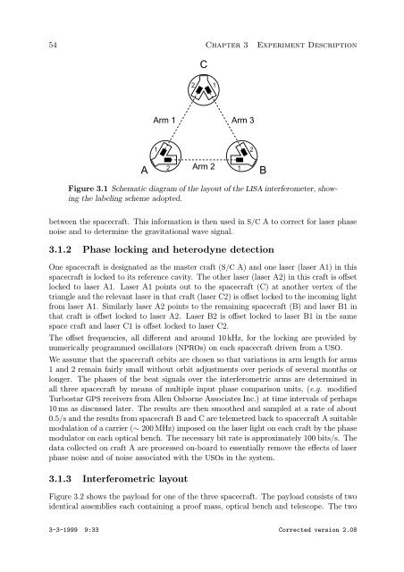
Figure 3.1 Schematic diagram of the layout of the LISA interferometer, showing<br />
the labeling scheme adopted.<br />
between the spacecraft. This information is then used in S/C A to correct for laser phase<br />
noise and to determine the gravitational wave signal.<br />
3.1.2 <strong>Phase</strong> locking and heterodyne detection<br />
One spacecraft is designated as the master craft (S/C A) and one laser (laser A1) in this<br />
spacecraft is locked to its reference cavity. The other laser (laser A2) in this craft is offset<br />
locked to laser A1. Laser A1 points out to the spacecraft (C) at another vertex of the<br />
triangle and the relevant laser in that craft (laser C2) is offset locked to the incoming light<br />
from laser A1. Similarly laser A2 points to the remaining spacecraft (B) and laser B1 in<br />
that craft is offset locked to laser A2. Laser B2 is offset locked to laser B1 in the same<br />
space craft and laser C1 is offset locked to laser C2.<br />
The offset frequencies, all different and around 10 kHz, for the locking are provided by<br />
numerically programmed oscillators (NPROs) on each spacecraft driven from a USO.<br />
We assume that the spacecraft orbits are chosen so that variations in arm length for arms<br />
1 and 2 remain fairly small without orbit adjustments over periods of several months or<br />
longer. The phases of the beat signals over the interferometric arms are determined in<br />
all three spacecraft by means of multiple input phase comparison units, (e.g. modified<br />
Turbostar GPS receivers from Allen Osborne Associates Inc.) at time intervals of perhaps<br />
10 ms as discussed later. The results are then smoothed and sampled at a rate of about<br />
0.5/s and the results from spacecraft B and C are telemetred back to spacecraft A suitable<br />
modulation of a carrier (∼ 200 MHz) imposed on the laser light on each craft by the phase<br />
modulator on each optical bench. The necessary bit rate is approximately 100 bits/s. The<br />
data collected on craft A are processed on-board to essentially remove the effects of laser<br />
phase noise and of noise associated with the USOs in the system.<br />
3.1.3 Interferometric layout<br />
Figure 3.2 shows the payload for one of the three spacecraft. The payload consists of two<br />
identical assemblies each containing a proof mass, optical bench and telescope. The two<br />
3-3-1999 9:33 Corrected version 2.08<br />
1<br />
2