View Document Here - Hanford Site
View Document Here - Hanford Site
View Document Here - Hanford Site
Create successful ePaper yourself
Turn your PDF publications into a flip-book with our unique Google optimized e-Paper software.
, ..,<br />
Appendix II - Detailed Description of Alternative 6: DoFJRl4001-11<br />
Close in Place - Collapsed Structu're Rev. jA^ft_L1<br />
n RC4Jis•L.S:;^kcrn,t<br />
1 Ii.1.4 Modify External Area<br />
2<br />
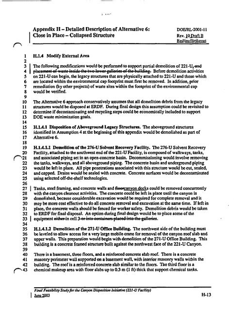
3 The following modifications would be performed to support partial demolition of 221-U,-and<br />
4 . Before demolition activities<br />
5 on 221-U can begin, the legacy structures that are physically attached to 221-U and those which<br />
6 are located within the environmental cop footprint must first be removed. In addition, prior<br />
7 remediation (by other projects) of waste sites within the footprint of the environmental cap<br />
8 would be verified.<br />
9<br />
10 The Alternative 6 approach conservatively assumes that all demolition debris from the legacy<br />
11 structures would be disposed at ERDF. During final design this assumption could be revisited to<br />
12 determine if decontaminating and recycling steps could be economically included to support<br />
13 DOE waste minimization goals.<br />
14<br />
15 H.1A.1 Disposition of Aboveground Legacy Structures. The aboveground structures<br />
16 identified in Assumption 4 at the beginning of this appendix would be demolished as part of<br />
17 Alternative 6.<br />
18<br />
19 H.1A.1.1 Demolition or the 276-U Solvent Recovery Facility. The 276-U Solvent Recovery<br />
20 Facility, attached to the southwest end of the 221-U Facility, is composed of walkways, tanks,<br />
('\21 and associated piping set in an opentoncrete basin. Decommissioning would involve removing<br />
22 the tanks, walkways, and all aboveground piping. The concrete basin and underground piping<br />
23 would be left in place. All pipe penetrations associated with this structure would be cut, sealed,<br />
24 and capped. Drains would be sealed with concrete. Concrete surfaces would be decontaminated<br />
25 using selected off-the-shelf technologies.<br />
26<br />
27 Tanks, steel framing, and concrete walls and Aeercanyon deck s could be removed concurrently<br />
28 with the canyon cleanout activities. The concrete could be left in place until the canyon is<br />
29 demolished, because considerable excavation would be required for complete removal and it<br />
30 may be more cost effective to do all concrete removal and excavation at the same time. If left in<br />
31 place, the concrete walls should be fenced for worker safety. Demolition debris would be taken<br />
32 to ERDF for final disposal. An option during final design would be to place some of the<br />
33 equipment eithetin cell<br />
34<br />
35 H.1.4.1.2 Demolition of the 271-U Office Building. The northwest side of the building must<br />
36 be leveled to allow access for a very large mobile crane for removal of the canyon roof slab and<br />
37 upper walls. This preparation would begin with demolition of the 271-U Office Building. This<br />
38 building is a concrete framed structure built against the northwest face of the 221-U Canyon.<br />
39<br />
40 There is a basement, three floors, and a reinfotced concrete slab roof. There is a concrete<br />
41 masonry perimeter wall supported on a basement wall, with interior masonry wa11s within the<br />
42 building. The roof is a reinforced concrete slab similar to the floors. The third floor is a<br />
('N 43 chemical makeup area with floor slabs up to 0.3 m(1 ft) thick that support chemical tanks.<br />
Final Feasibility Sludyjor the Canyon Disposition lniriotive (221-U Facility)<br />
June '100 H-13


