View Document Here - Hanford Site
View Document Here - Hanford Site
View Document Here - Hanford Site
You also want an ePaper? Increase the reach of your titles
YUMPU automatically turns print PDFs into web optimized ePapers that Google loves.
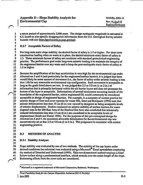
Appendix D - Slope Stability Analysis for poEIRL-2001-11<br />
I Environmental Cap Rev. 0 1 Draft a<br />
^ Redline/Slrikeout<br />
I a return period of approximately 2.000 years. The design earthquake magnitude is estimated at<br />
2 6.5, based on site-specific deaggregation information from the U.S. Geological Survey seismic<br />
3 hazards web site (httn://@eohazards.cr.usgs. fov/eq) .<br />
4<br />
5 D.2.7 Acceptable Factors of Safety<br />
6<br />
7 For long-term static slope stability, the desired factor of safety is 1.5 or higher. For short-term<br />
8 construction loading when no waste is in place, the desired minimum static factor of safety is<br />
9 1.3. These minimum factors of safety are consistent with standard geotechnical engineering<br />
10 practice. The performance goal under long-term seismic loading is to maintain the integrity of<br />
12 the engineered barrier over any waste and to keep the post-earthquake static factor of safety at<br />
12 1.5 or higher.<br />
13<br />
14 Because the amplification of the base acceleration is very high for the environmental cap under<br />
15 Alternatives 3 and 4 ( and particularly for the engineered surface barrier), it is judged that there<br />
16 would likely be some amount of movement ( i.e., the factor of safety under seismic loading is less<br />
17 than 1.0) for any reasonable environmental cap configuration. Such movement is acceptable as<br />
18 long as the goals listed above are met. It was judged that 2.5 or 5.0 cm (1 or 2 in.) of<br />
19 deformation that is primarily horizontal within the silt barrier layers and does not penetrate the<br />
20 bottom of the layer is acceptable. Deformations of several centimeters occurring outside of the<br />
^21 boundaries of the engineered barsier, within engineered fill, would commonly be considered<br />
22 acceptable in design of engineered barriers. For example, in a summary of current practice for<br />
23 seismic design of liner and cover systems for waste fills, Seed and Bonaparte ( 1992) note that<br />
24 seismic deformations less than 15 cm (6 in.) are viewed by designers as being acceptable levels<br />
25 of seismic displacement. Studies conducted on seismic stability of surface barriers for waste<br />
26 disposal sites in the 200 East Area of the <strong>Hanford</strong> <strong>Site</strong> have also concluded that seismically<br />
27 induced deformations less than 15 cm (6 in.) are considered to be acceptable levels of<br />
28 displacement ( Saleh and Daniel 1994). For the purposes of this pre-conceptual design for<br />
29 Alternatives 3 and 4, the maximum allowable deformation for the environmental cap was<br />
30 conservatively set at that 2.5 or 5.0 cm ( I to 2 in.). This judgement is consistent with current<br />
31 engineering practice.<br />
32<br />
33<br />
34 D3 METHODS OF ANALYSIS<br />
35<br />
36 D3.1 Stability Analyses<br />
37<br />
38 Slope stability was evaluated by one of two methods. The stabilitX of the cap layers under<br />
39 drained conditions (no cohesion) was evaluated using a Microsoft Excel spreadsheet employing<br />
40 the method of Druschel and Underwood ( 1993). This two-dimensional method employs a fixed<br />
41 failure surface along a predetermined interface, which extends over the entire length of the slope.<br />
^42 Buttressing effects from the cover soils are considered.<br />
° Miaosoft Is a registered trademark of Microsoft Corporation, Redmond, Washington.<br />
Final Feasibility Study for the Canyon Disposition Initiative ( 221•U Facility)<br />
it•+ D-5


