1 - page screenshot of chlodzenie.pl
1 - page screenshot of chlodzenie.pl
1 - page screenshot of chlodzenie.pl

Create successful ePaper yourself
Turn your PDF publications into a flip-book with our unique Google optimized e-Paper software.
Air tight test 5CSL0-06B<br />
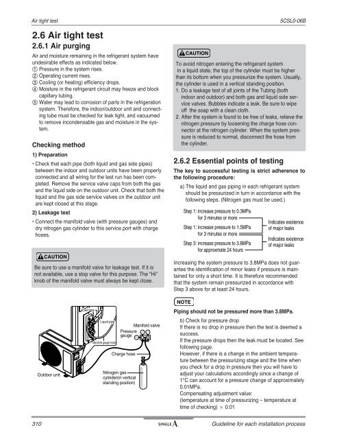
2.6 Air tight test<br />
2.6.1 Air purging<br />
Air and moisture remaining in the refrigerant system have<br />
undesirable effects as indicated below.<br />
① Pressure in the system rises.<br />
② Operating current rises.<br />
③ Cooling (or heating) efficiency drops.<br />
④ Moisture in the refrigerant circuit may freeze and block<br />
capillary tubing.<br />
⑤ Water may lead to corrosion <strong>of</strong> parts in the refrigeration<br />
system. Therefore, the indoor/outdoor unit and connecting<br />
tube must be checked for leak tight, and vacuumed<br />
to remove incondensable gas and moisture in the system.<br />
Checking method<br />
1) Preparation<br />
• Check that each pipe (both liquid and gas side pipes)<br />
between the indoor and outdoor units have been properly<br />
connected and all wiring for the test run has been com<strong>pl</strong>eted.<br />
Remove the service valve caps from both the gas<br />
and the liquid side on the outdoor unit. Check that both the<br />
liquid and the gas side service valves on the outdoor unit<br />
are kept closed at this stage.<br />
2) Leakage test<br />
• Connect the manifold valve (with pressure gauges) and<br />
dry nitrogen gas cylinder to this service port with charge<br />
hoses.<br />
CAUTION<br />
Be sure to use a manifold valve for leakage test. If it is<br />
not available, use a stop valve for this purpose. The "Hi"<br />
knob <strong>of</strong> the manifold valve must always be kept close.<br />
Outdoor unit<br />
Gas Pipe pipe Pipe<br />
Liquid Pipe<br />
pipe<br />
Manifold gauge hose<br />
Manifold valve<br />
Pressure<br />
gauge<br />
Charge hose<br />
Nitrogen gas<br />
cylinder(in vertical<br />
standing position)<br />
Lo Hi<br />
CAUTION<br />
To avoid nitrogen entering the refrigerant system<br />
in a liquid state, the top <strong>of</strong> the cylinder must be higher<br />
than its bottom when you pressurize the system. Usually,<br />
the cylinder is used in a vertical standing position.<br />
1. Do a leakage test <strong>of</strong> all joints <strong>of</strong> the Tubing (both<br />
indoor and outdoor) and both gas and liquid side service<br />
valves. Bubbles indicate a leak. Be sure to wipe<br />
<strong>of</strong>f the soap with a clean cloth.<br />
2. After the system is found to be free <strong>of</strong> leaks, relieve the<br />
nitrogen pressure by loosening the charge hose connector<br />
at the nitrogen cylinder. When the system pressure<br />
is reduced to normal, disconnect the hose from<br />
the cylinder.<br />
2.6.2 Essential points <strong>of</strong> testing<br />
The key to successful testing is strict adherence to<br />
the following procedure:<br />
a) The liquid and gas piping in each refrigerant system<br />
should be pressurized in turn in accordance with the<br />
following steps. (Nitrogen gas must be Manifold used.) gauge<br />
Step 1: increase pressure to 0.3MPa<br />
for 3 minutes or more<br />
Step 1: increase pressure to 1.5MPa<br />
for 3 minutes or more<br />
Step 3: increase pressure to 3.8MPa<br />
for approxmate 24 hours<br />
Liquid Pipe<br />
Indicates existence<br />
<strong>of</strong> major leaks<br />
Indicates existence<br />
<strong>of</strong> major leaks<br />
310 Guideline for each installation process<br />
Gas Pipe<br />
Increasing the system pressure to 3.8MPa does not guarantee<br />
the identification <strong>of</strong> minor leaks if pressure is maintained<br />
for only a short time. It is therefore recommended<br />
that the system remain pressurized in accordance with<br />
Step 3 above for at least 24 hours.<br />
NOTE<br />
Piping should not be pressured more than 3.8MPa.<br />
b) Check for pressure drop<br />
If there is no drop in pressure then the test is deemed a<br />
success.<br />
If the pressure drops then the leak must be located. See<br />
following <strong>page</strong>.<br />
However, if there is a change in the ambient temperature<br />
between the pressurizing stage and the time when<br />
you check for a drop in pressure then you will have to<br />
adjust your calculations accordingly since a change <strong>of</strong><br />
1°C can account for a pressure change <strong>of</strong> approximately<br />
0.01MPa.<br />
Compensating adjustment value:<br />
(temperature at time <strong>of</strong> pressurizing – temperature at<br />
time <strong>of</strong> checking) × 0.01