WSCAD51 Getting Started - FTP Directory Listing
WSCAD51 Getting Started - FTP Directory Listing
WSCAD51 Getting Started - FTP Directory Listing

You also want an ePaper? Increase the reach of your titles
YUMPU automatically turns print PDFs into web optimized ePapers that Google loves.
Creating a symbol<br />
To complete the exercise we will create a symbol, for this example, a two pole circuit<br />
breaker switch.<br />
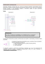
In the symbol editor it is possible to assemble several symbols together to create a new<br />
one. However, you cannot take a 1 pole circuit breaker and a 1 pole NC contact joining<br />
them together as a 2 pole switch because the automa tic function would detect them as<br />
two different components!<br />
The following explains the fundamental methods of generating symbols with the symbol<br />
editor. Please follow the steps required.<br />
A symbol that can be used with the automatic functions is defined by:<br />
Component<br />
graphic<br />
Pins<br />
determines visual shape or form of the symbol<br />
determines the symbol connection points, and<br />
line breaking.<br />
Component name name in the library<br />
Reference name unique name in the drawing<br />
Component type<br />
determines how the Automatic functions handle<br />
the symbol<br />
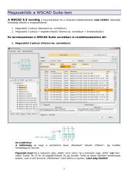
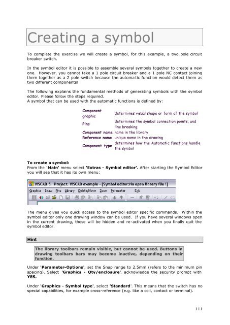
To create a symbol:<br />
From the 'Main' menu select 'Extras - Symbol editor'. After starting the Symbol Editor<br />
you will see that it has its own menu:<br />
The menu gives you quick access to the symbol editor specific commands. Within the<br />
symbol editor only one drawing window can be used. If you have several windows open<br />
in the current drawing, these will be hidden and re-activated when you finally quit the<br />
symbol editor.<br />
Hint<br />
The library toolbars remain visible, but cannot be used. Buttons in<br />
drawing toolbars bars may become inactive, depending on their<br />
function.<br />
Under 'Parameter-Options', set the Snap range to 2.5mm (refers to the minimum pin<br />
spacing). Select 'Graphics - Qty/enclosure', acknowledge the security prompt with<br />
YES.<br />
Under 'Graphics - Symbol type', select 'Standard'. This means that the switch has no<br />
special capabilities, for example cross-reference (e.g. like a coil, contact or terminal).<br />
111