WSCAD51 Getting Started - FTP Directory Listing
WSCAD51 Getting Started - FTP Directory Listing
WSCAD51 Getting Started - FTP Directory Listing

Create successful ePaper yourself
Turn your PDF publications into a flip-book with our unique Google optimized e-Paper software.
<strong>Getting</strong> <strong>Started</strong><br />
Position the cursor over the cross-reference text and click with the right mouse button:<br />
The cross-reference navigator immediately loads the correct page of your drawing and<br />
positions the cursor near to the corresponding contact.<br />
Click with the right mouse button on the cross-reference text at the left side of the<br />
contact, and the navigator brings you back to the page with the coil.<br />
Hint<br />
62<br />
The cross-reference navigator also works with line related crossreferences.<br />
PLC Manager<br />
General<br />
In the Professional version the individual Bits of the inputs and outputs of PLC modules<br />
can be loaded on different pages of the circuit diagram (page 2 of this practice<br />
example). The individual PLC inputs and outputs are collated into a central overview<br />
table, with cross-references and PLC comment texts (page 3 of this practice example).<br />
This allows very flexible design and display, not only during the design stage but also in<br />
subsequent modifications to the equipment.<br />
Hint<br />
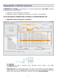
WSCAD offers two different ways of to load PLC symbols.<br />
First you load the PLC main module<br />
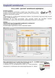
One of the main advantages of the PLC manager is the clear representation of all PLC<br />
channels. To demonstrate this, go to page 3 of your practice example (via 'File – page<br />
up/dn' or simply by pressing the button).<br />
First, load the drawing macro 'PLC-CPU315-2DP.0000' - 'File – Insert drawing<br />
macro' and position it at 52.5 / 185.0 mm. This pre-prepared macro contains the<br />
supply connections for the PLC main modules.<br />
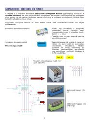
Next, activate the Favourites library 'EXAMPLE' then load the symbol 'Digital Input<br />
SM 321-1BH00 16x24V DC' command 'Schematic – Load symbol ...' on the<br />
coordinates 132.5 / 147.5 mm. The database selection appears. Select the module<br />
'Digital Input SM 321-1BH00 16x24V DC’. In the following menu 'Component<br />
Parameters' enter the function text '!Motor control'. Note the preceding '!', which<br />
makes the text invisible, and place the text anywhere you wish. Exit the Symbol Explorer<br />
with 'Exit'.<br />
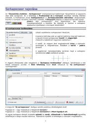
Now set the individual (PLC) inputs and outputs<br />
Go back to Page 2 in order to position the individual inputs and outputs.<br />
Load the symbol 'Digital Input'. Position it with a double click (or )<br />
exactly over the coil 'Feed forward' on the coordinates 165.0 / 170.0 mm and you will<br />
get the 'PLC selection' dialog with all available PLC main modules of the PLC manager.<br />
Select the card '!Motor Control' and you see all channels of this unit.