WSCAD51 Getting Started - FTP Directory Listing
WSCAD51 Getting Started - FTP Directory Listing
WSCAD51 Getting Started - FTP Directory Listing

You also want an ePaper? Increase the reach of your titles
YUMPU automatically turns print PDFs into web optimized ePapers that Google loves.
<strong>Getting</strong> <strong>Started</strong><br />
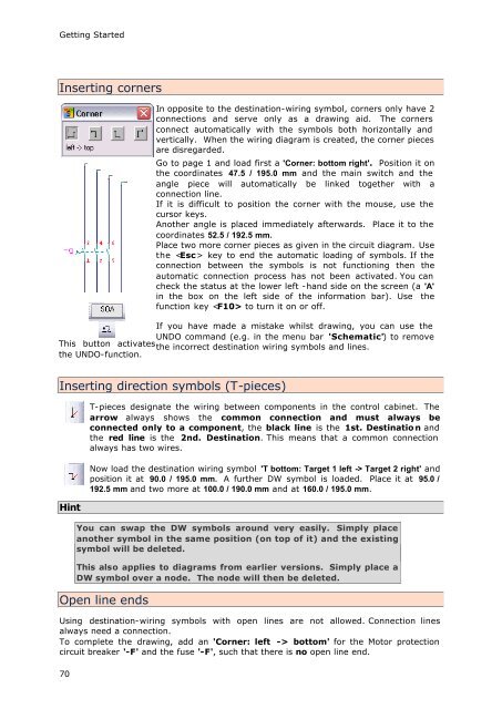
Inserting corners<br />
This button activates<br />
the UNDO-function.<br />
70<br />
In opposite to the destination-wiring symbol, corners only have 2<br />
connections and serve only as a drawing aid. The corners<br />
connect automatically with the symbols both horizontally and<br />
vertically. When the wiring diagram is created, the corner pieces<br />
are disregarded.<br />
Go to page 1 and load first a 'Corner: bottom right'. Position it on<br />
the coordinates 47.5 / 195.0 mm and the main switch and the<br />
angle piece will automatically be linked together with a<br />
connection line.<br />
If it is difficult to position the corner with the mouse, use the<br />
cursor keys.<br />
Another angle is placed immediately afterwards. Place it to the<br />
coordinates 52.5 / 192.5 mm.<br />
Place two more corner pieces as given in the circuit diagram. Use<br />
the key to end the automatic loading of symbols. If the<br />
connection between the symbols is not functioning then the<br />
automatic connection process has not been activated. You can<br />
check the status at the lower left -hand side on the screen (a 'A'<br />
in the box on the left side of the information bar). Use the<br />
function key to turn it on or off.<br />
If you have made a mistake whilst drawing, you can use the<br />
UNDO command (e.g. in the menu bar 'Schematic') to remove<br />
the incorrect destination wiring symbols and lines.<br />
Inserting direction symbols (T-pieces)<br />
Hint<br />
T-pieces designate the wiring between components in the control cabinet. The<br />
arrow always shows the common connection and must always be<br />
connected only to a component, the black line is the 1st. Destinatio n and<br />
the red line is the 2nd. Destination. This means that a common connection<br />
always has two wires.<br />
Now load the destination wiring symbol 'T bottom: Target 1 left -> Target 2 right' and<br />
position it at 90.0 / 195.0 mm. A further DW symbol is loaded. Place it at 95.0 /<br />
192.5 mm and two more at 100.0 / 190.0 mm and at 160.0 / 195.0 mm.<br />
You can swap the DW symbols around very easily. Simply place<br />
another symbol in the same position (on top of it) and the existing<br />
symbol will be deleted.<br />
This also applies to diagrams from earlier versions. Simply place a<br />
DW symbol over a node. The node will then be deleted.<br />
Open line ends<br />
Using destination-wiring symbols with open lines are not allowed. Connection lines<br />
always need a connection.<br />
To complete the drawing, add an 'Corner: left -> bottom' for the Motor protection<br />
circuit breaker '-F' and the fuse '-F', such that there is no open line end.