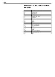
519FLA REPAIR MANUAL
519FLA REPAIR MANUAL
519FLA REPAIR MANUAL

Create successful ePaper yourself
Turn your PDF publications into a flip-book with our unique Google optimized e-Paper software.
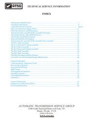
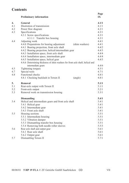
Contents<br />
Page<br />
Preliminary information IX<br />
4. General 4.1/1<br />
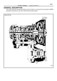
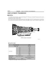
4.1 Illustration of transmission 4.1/1<br />
4.2 Power flow diagram 4.2/1<br />
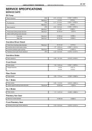
4.3 Specifications 4.3/1<br />
4.3.1 Screw specifications 4.3/1<br />
4.3.1.1 Transfer box housing 4.3/1<br />
4.4 Adjusting work 4.4/1<br />
4.4.0 Preparations for bearing adjustment (shim washers) 4.4/1<br />
4.4.1 Bearing projection, front axle shaft 4.4/2<br />
4.4.2 Bearing projection, helical/intermediate gear 4.4/3<br />
4.4.3 Installation space, front axle shaft 4.4/4<br />
4.4.4 Installation space, intermediate gear 4.4/4<br />
4.4.5 Installation space, helical gear 4.4/5<br />
4.4.6 Determining thickness of shim washers for front axle shaft, helical and<br />
intermediate gears 4.4/6<br />
4.5 Tightening torques 4.5/1<br />
4.7 Special tools 4.7/1<br />
4.8 Functional checks 4.8/1<br />
4.8.1 Checking backlash in Torsen II (angle) 4.8/1<br />
5. Removal 5.1/1<br />
5.1 Rear-axle output with Torsen II 5.1/1<br />
5.2 Front-axle output 5.2/1<br />
5.3 Removal work on transmission housing 5.3/1<br />
Dismantling 5.4/1<br />
5.4 Helical and intermediate gears and front axle shaft 5.4/1<br />
5.4.1 Helical gear 5.4/1<br />
5.4.2 Intermediate gear 5.4/1<br />
5.4.3 Front axle shaft 5.4/1<br />
5.5 Housing sections 5.5/1<br />
5.5.1 Intermediate housing 5.5/1<br />
5.5.2 Vibration damper 5.5/1<br />
5.5.3 Dismantling transfer box housing 5.5/1<br />
5.5.4 Removing both needle roller sleeves 5.5/3<br />
5.6 Rear axle shaft and output gear 5.6/1<br />
5.6.1 Rear axle shaft 5.6/1<br />
5.6.2 Output gear 5.6/1<br />
5.7 Dismantling Torsen II 5.7/1<br />
00/08/01 5 HP 19 FLA © ZF Getriebe GmbH Saarbrücken CD<br />
VII