- Page 1 and 2: Versione00/08/01 CD REPAIR MANUAL 5
- Page 3 and 4: Contents Page Preliminary informati
- Page 5 and 6: 3. Installation 3.1/1 Adjustments 3
- Page 7: Note: This manual treats the valve
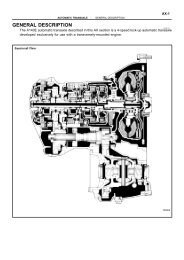
- Page 11: 1.2 Power flow diagram 1st GEAR Inp
- Page 14 and 15: 1.3.1.3Tightening yield strength cr
- Page 16 and 17: Check the value on the force measur
- Page 18 and 19: Example (for 1.4.1.1): F = 1.48 mm
- Page 20 and 21: Example (for 1.4.1.2): F = 1.48 mm
- Page 22 and 23: Example (for 1.4.1.3): F = 1.48 mm
- Page 24 and 25: Example (for 1.4.1.4): F = 1.48 mm
- Page 26 and 27: Example (for 1.4.1.5): F = 1.48 mm
- Page 28 and 29: Example (for 1.4.1.6): F = 1.48 mm
- Page 30 and 31: Example: (for 1.4.1.7) F = 1.48 mm
- Page 32 and 33: Tighten the differential cover with
- Page 34 and 35: Example: MD MU MO = 0.38 mm (preloa
- Page 36 and 37: Place the differential-side inner b
- Page 40 and 41: 1.4.4 Detent spring switch Using a
- Page 42 and 43: 1.4.5.2 Pinion projection Insert th
- Page 44 and 45: 1.4.6 Bearing adjustment, output ge
- Page 46 and 47: 1.4.6.2 Projection, helical/interme
- Page 48 and 49: 1.4.6.5 Installation space, helical
- Page 50 and 51: Example: (for 1.4.6) Pinion: KRR =
- Page 52 and 53: Example (for 1.4.7): M1 = 0.88 mm M
- Page 54 and 55: No. Designation Part List- Wrench s
- Page 57 and 58: 1.7 Special tools 98008 98034 00045
- Page 59 and 60: 00108 00053 97301 OBJECT Order-No.
- Page 61 and 62: 99250 99265 99274 OBJECT Order-No.
- Page 63 and 64: 99262 98002 99259 OBJECT Order-No.
- Page 65 and 66: 98395 91199 92223 OBJECT Order-No.
- Page 67 and 68: 99264 00054 99256 OBJECT Order-No.
- Page 69 and 70: 99257 99253 00063 OBJECT Order-No.
- Page 71 and 72: 98399 98400 98401 OBJECT Order-No.
- Page 73 and 74: 98405 98148 98406 OBJECT Order-No.
- Page 75 and 76: 99246 00059 00060 OBJECT Order-No.
- Page 77 and 78: 00065 00066 00067 OBJECT Order-No.
- Page 79 and 80: 00071 99249 00061 OBJECT Order-No.
- Page 81 and 82: 97305 98155 99271 OBJECT Order-No.
- Page 83 and 84: 99270 00072 00062 OBJECT Order-No.
- Page 85: 1.8 Oilflow chart (position N accor
- Page 88 and 89:
2.1.2 Removing front axle output Ta
- Page 90 and 91:
Unscrew and remove the 17 large-hea
- Page 92 and 93:
Drive the clamping sleeve out of th
- Page 94 and 95:
Remove the 12 differential cover sc
- Page 97 and 98:
99076 99077 99078 00/08/01 5 HP 19
- Page 99:
99082 99083 00/08/01 5 HP 19 FL ©
- Page 102 and 103:
Use pliers 5x46 001 376 to remove t
- Page 104 and 105:
2.6.3 Front axle housing Pull the b
- Page 106 and 107:
2.6.6.3 Pinion Using puller 5x46 50
- Page 109 and 110:
99105 99106 99107 2.7 Tower 00/08/0
- Page 111 and 112:
99109 99110 98409 2.7.2 Clutch F 00
- Page 113 and 114:
99114 99115 99116 00/08/01 5 HP 19
- Page 115 and 116:
99118 99119 99120 2.8 Input 00/08/0
- Page 117 and 118:
99121 99122 99123 2.8.2 Clutch A Ex
- Page 119 and 120:
99124 99126 99127 00/08/01 5 HP 19
- Page 121:
99131 98270 99133 00/08/01 5 HP 19
- Page 124 and 125:
Adjustment overview Note: During tr
- Page 126 and 127:
3.1.2 Front axle housing and front
- Page 128 and 129:
3.1.4 Installing pinion shaft in tr
- Page 130 and 131:
Attach magnet 35.150/140 to oil dam
- Page 133 and 134:
3.2 Installing shift and parking lo
- Page 135 and 136:
99161 00027 99164 00/08/01 5 HP 19
- Page 137 and 138:
3.3 Tower, installing tower 3.3.1 P
- Page 139 and 140:
98287 00/08/01 /110 /130 /140 /120
- Page 141 and 142:
99172 /200 /190 /110 /180 /170 73.1
- Page 143 and 144:
99173 99174 99176 00/08/01 5 HP 19
- Page 145 and 146:
00031 99180 99181 00/08/01 5 HP 19
- Page 147 and 148:
3.4 Installing front axle output 99
- Page 149 and 150:
3.5 Planetary gear sets I and II 99
- Page 151 and 152:
99191 99192 99193 Insert thrust was
- Page 153:
99197 00/08/01 5 HP 19 FL © ZF Get
- Page 156 and 157:
Place cup spring 71.080 on piston E
- Page 158 and 159:
3.6.2 Clutch A /110 /120 /190 /130
- Page 160 and 161:
Pull O-ring 71.160 on to ring 71.17
- Page 162 and 163:
Insert cup spring 72.110, press the
- Page 165 and 166:
3.7 Oil supply and brake C and inst
- Page 167 and 168:
99210 99211 99212 00/08/01 5 HP 19
- Page 169 and 170:
99218 99219 99220 00/08/01 5 HP 19
- Page 171 and 172:
3.8 Adding parts to flange shaft an
- Page 173:
00037 99229 00038 00/08/01 5 HP 19
- Page 176 and 177:
Insert 5 sealing sleeves 01.270 int
- Page 178 and 179:
Attach oil filter 27.420 to the val
- Page 180 and 181:
3.9.2 Installing position switch an
- Page 182 and 183:
Fasten converter retaining bracket
- Page 184 and 185:
subject to alterations © Copyright
- Page 186 and 187:
6. Installation 6.1/1 6.1 Torsen II
- Page 188 and 189:
Warning: The transmission, differen
- Page 191:
4.2 Power flow diagram 2nd GEAR 4th
- Page 195 and 196:
99038 99039 00094 00/08/01 5 HP 19
- Page 197 and 198:
00098 00/08/01 5 HP 19 FLA © ZF Ge
- Page 199 and 200:
00015 00016 00/08/01 5 HP 19 FLA ©
- Page 201:
Example: (for 4.4) Front axle shaft
- Page 205 and 206:
4.7 Special tools 00053 99265 00073
- Page 207 and 208:
99276 99277 98171 OBJECT Order-No.
- Page 209 and 210:
00057 00065 00066 OBJECT Order-No.
- Page 211 and 212:
00077 99281 99280 OBJECT Order-No.
- Page 213 and 214:
00081 00082 00083 OBJECT Order-No.
- Page 215 and 216:
98150 98155 99268 OBJECT Order-No.
- Page 217 and 218:
00090 00089 00/08/01 5 HP 19 FLA ©
- Page 219 and 220:
99243 99244 99003 00/08/01 5 HP 19
- Page 221:
99005 99006 00/08/01 5 HP 19 FLA ©
- Page 225:
99008 99009 99010 00/08/01 5 HP 19
- Page 228 and 229:
Using drift 5x46 002 277, force the
- Page 231:
99018 99019 00/08/01 5 HP 19 FLA ©
- Page 234 and 235:
Take off the thrust washer. Raise t
- Page 236 and 237:
Place the cover with the larger nee
- Page 238 and 239:
By turning the sun gear in either d
- Page 240 and 241:
6.2.1.1 Output gear Using sleeve 5x
- Page 242 and 243:
Install vibration damper 36.230 on
- Page 244 and 245:
6.2.2 Adding parts to transmission
- Page 246:
Secure the transfer box housing to