Coherent Backscattering from Multiple Scattering Systems - KOPS ...
Coherent Backscattering from Multiple Scattering Systems - KOPS ...
Coherent Backscattering from Multiple Scattering Systems - KOPS ...

You also want an ePaper? Increase the reach of your titles
YUMPU automatically turns print PDFs into web optimized ePapers that Google loves.
3.2 Wide Angle Setup<br />
1 .0<br />
0 .8<br />
h e lic ity c o n s e rv in g<br />
h e lic ity b re a k in g<br />
0 .6<br />
c o o p e ro n<br />
0 .4<br />
0 .2<br />
0 .0<br />
-9 0 -6 0 -3 0 0 3 0 6 0 9 0<br />
s c a tte rin g a n g le [d e g ]<br />
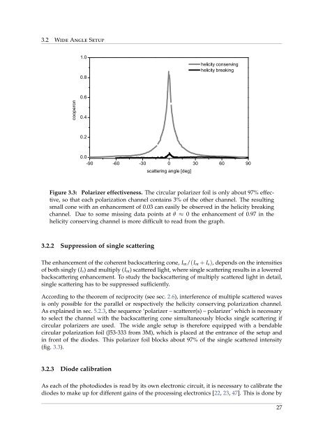
Figure 3.3: Polarizer effectiveness. The circular polarizer foil is only about 97% effective,<br />
so that each polarization channel contains 3% of the other channel. The resulting<br />
small cone with an enhancement of 0.03 can easily be observed in the helicity breaking<br />
channel. Due to some missing data points at θ ≈ 0 the enhancement of 0.97 in the<br />
helicity conserving channel is more difficult to read <strong>from</strong> the graph.<br />
3.2.2 Suppression of single scattering<br />
The enhancement of the coherent backscattering cone, I m /(I m + I s ), depends on the intensities<br />
of both singly (I s ) and multiply (I m ) scattered light, where single scattering results in a lowered<br />
backscattering enhancement. To study the backscattering of multiply scattered light in detail,<br />
single scattering has to be suppressed sufficiently.<br />
According to the theorem of reciprocity (see sec. 2.6), interference of multiple scattered waves<br />
is only possible for the parallel or respectively the helicity conserving polarization channel.<br />
As explained in sec. 5.2.3, the sequence ‘polarizer – scatterer(s) – polarizer’ which is necessary<br />
to select the channel with the backscattering cone simultaneously blocks single scattering if<br />
circular polarizers are used. The wide angle setup is therefore equipped with a bendable<br />
circular polarization foil (J53-333 <strong>from</strong> 3M), which is placed at the entrance of the setup and<br />
in front of the diodes. This polarizer foil blocks about 97% of the single scattered intensity<br />
(fig. 3.3).<br />
3.2.3 Diode calibration<br />
As each of the photodiodes is read by its own electronic circuit, it is necessary to calibrate the<br />
diodes to make up for different gains of the processing electronics [22, 23, 47]. This is done by<br />
27