Coherent Backscattering from Multiple Scattering Systems - KOPS ...
Coherent Backscattering from Multiple Scattering Systems - KOPS ...
Coherent Backscattering from Multiple Scattering Systems - KOPS ...

You also want an ePaper? Increase the reach of your titles
YUMPU automatically turns print PDFs into web optimized ePapers that Google loves.
3 Setups<br />
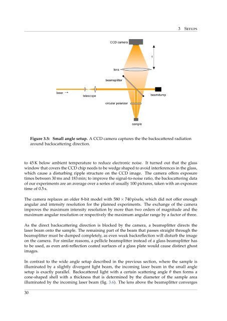
Figure 3.5: Small angle setup. A CCD camera captures the the backscattered radiation<br />
around backscattering direction.<br />
to 45 K below ambient temperature to reduce electronic noise. It turned out that the glass<br />
window that covers the CCD chip needs to be wedge shaped to avoid interferences in the glass,<br />
which cause a disturbing ripple structure on the CCD image. The camera offers exposure<br />
times between 30 ms and 183 min; to improve the signal-to-noise ratio, the backscattering data<br />
of our experiments are an average over a series of usually 100 pictures, taken with an exposure<br />
time of 0.5 s.<br />
The camera replaces an older 8-bit model with 580 × 740 pixels, which did not offer enough<br />
angular and intensity resolution for the planned experiments. The exchange of the camera<br />
improves the maximum intensity resolution by more than two orders of magnitude and the<br />
maximum angular resolution or respectively the maximum angular range by a factor of three.<br />
As the direct backscattering direction is blocked by the camera, a beamsplitter directs the<br />
laser beam onto the sample. The remaining part of the beam that passes straight through the<br />
beamsplitter must be dumped completely, as even weak backreflection will disturb the image<br />
on the camera. For similar reasons, a pellicle beamsplitter instead of a glass beamsplitter has<br />
to be used, as even anti-reflection coated surfaces of a glass plate would cause distinct ghost<br />
images.<br />
In contrast to the wide angle setup described in the previous section, where the sample is<br />
illuminated by a slightly divergent light beam, the incoming laser beam in the small angle<br />
setup is exactly parallel. Backscattered light with a certain scattering angle θ then forms a<br />
cone-shaped shell with a thickness that is determined by the diameter of the sample area<br />
illuminated by the incoming laser beam (fig. 3.6). The lens above the beamsplitter converges<br />
30