Coherent Backscattering from Multiple Scattering Systems - KOPS ...
Coherent Backscattering from Multiple Scattering Systems - KOPS ...
Coherent Backscattering from Multiple Scattering Systems - KOPS ...

You also want an ePaper? Increase the reach of your titles
YUMPU automatically turns print PDFs into web optimized ePapers that Google loves.
5 Experiments<br />
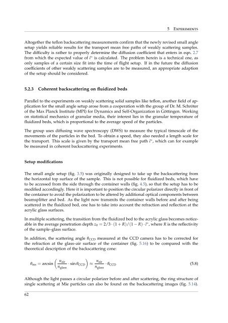
Altogether the teflon backscattering measurements confirm that the newly revised small angle<br />
setup yields reliable results for the transport mean free paths of weakly scattering samples.<br />
The difficulty is rather to properly determine the diffusion coefficient that enters in eqn. 2.7<br />
<strong>from</strong> which the expected value of l ∗ is calculated. The problem herein is a technical one, as<br />
only samples of a certain size fit into the time of flight setup. If in the future the diffusion<br />
coefficients of other weakly scattering samples are to be measured, an appropriate adaption<br />
of the setup should be considered.<br />
5.2.3 <strong>Coherent</strong> backscattering on fluidized beds<br />
Parallel to the experiments on weakly scattering solid samples like teflon, another field of application<br />
for the small angle setup arose <strong>from</strong> a cooperation with the group of Dr. M. Schröter<br />
of the Max Planck Institute (MPI) for Dynamics and Self-Organization in Göttingen. Working<br />
on statistical mechanics of granular media, their interest lies in the granular temperature of<br />
fluidized beds, which is proportional to the average speed of the particles.<br />
The group uses diffusing wave spectroscopy (DWS) to measure the typical timescale of the<br />
movements of the particles in the bed. To obtain a speed, they also needed a length scale for<br />
the transport. This scale is given by the transport mean free path l ∗ , which can for example<br />
be measured in coherent backscattering experiments.<br />
Setup modifications<br />
The small angle setup (fig. 3.5) was originally designed to take up the backscattering <strong>from</strong><br />
the horizontal top surface of the sample. This is not possible for fluidized beds, which have<br />
to be accessed <strong>from</strong> the side through the container walls (fig. 4.5), so that the setup has to be<br />
modified accordingly. Here it is important to position the circular polarizer directly in front of<br />
the container to avoid the polarization to be altered by additional optical components between<br />
beamsplitter and bed. As the light now transmits the container walls before and after being<br />
scattered in the fluidized bed, one has to take into account the refraction and reflection at the<br />
acrylic glass surfaces.<br />
In multiple scattering, the transition <strong>from</strong> the fluidized bed to the acrylic glass becomes noticeable<br />
in the average penetration depth z 0 = 2/3 · (1 + R)/(1 − R) · l ∗ , where R is the reflectivity<br />
of the sample–glass surface.<br />
In addition, the scattering angle θ CCD measured at the CCD camera has to be corrected for<br />
the refraction at the glass–air surface of the container (fig. 5.16) to be compared with the<br />
theoretical description of the backscattering cone:<br />
( )<br />
nair<br />
θ ms = arcsin · sin θ CCD ≈ n air<br />
· θ CCD (5.8)<br />
n glass n glass<br />
Although the light passes a circular polarizer before and after scattering, the ring structure of<br />
single scattering at Mie particles can also be found on the backscattering images (fig. 5.14).<br />
62