Coherent Backscattering from Multiple Scattering Systems - KOPS ...
Coherent Backscattering from Multiple Scattering Systems - KOPS ...
Coherent Backscattering from Multiple Scattering Systems - KOPS ...

Create successful ePaper yourself
Turn your PDF publications into a flip-book with our unique Google optimized e-Paper software.
5 Experiments<br />
220<br />
200<br />
180<br />
l* [µm]<br />
160<br />
140<br />
120<br />
100<br />
2 4 6 8 10 12 14 16<br />
lens position [mm]<br />
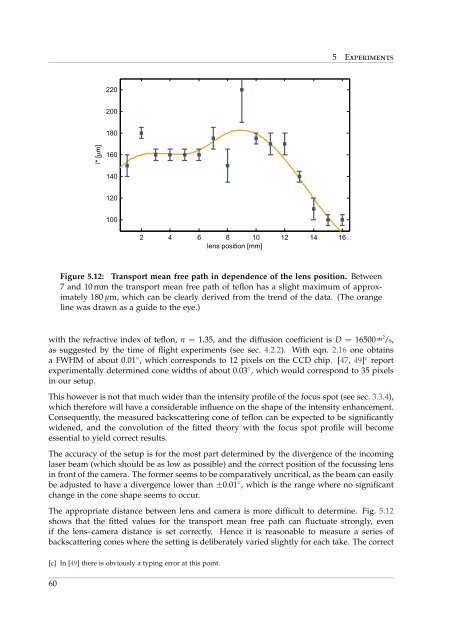
Figure 5.12: Transport mean free path in dependence of the lens position. Between<br />
7 and 10 mm the transport mean free path of teflon has a slight maximum of approximately<br />
180 µm, which can be clearly derived <strong>from</strong> the trend of the data. (The orange<br />
line was drawn as a guide to the eye.)<br />
with the refractive index of teflon, n = 1.35, and the diffusion coefficient is D = 16500 m2 /s,<br />
as suggested by the time of flight experiments (see sec. 4.2.2). With eqn. 2.16 one obtains<br />
a FWHM of about 0.01 ◦ , which corresponds to 12 pixels on the CCD chip. [47, 49] c report<br />
experimentally determined cone widths of about 0.03 ◦ , which would correspond to 35 pixels<br />
in our setup.<br />
This however is not that much wider than the intensity profile of the focus spot (see sec. 3.3.4),<br />
which therefore will have a considerable influence on the shape of the intensity enhancement.<br />
Consequently, the measured backscattering cone of teflon can be expected to be significantly<br />
widened, and the convolution of the fitted theory with the focus spot profile will become<br />
essential to yield correct results.<br />
The accuracy of the setup is for the most part determined by the divergence of the incoming<br />
laser beam (which should be as low as possible) and the correct position of the focussing lens<br />
in front of the camera. The former seems to be comparatively uncritical, as the beam can easily<br />
be adjusted to have a divergence lower than ±0.01 ◦ , which is the range where no significant<br />
change in the cone shape seems to occur.<br />
The appropriate distance between lens and camera is more difficult to determine. Fig. 5.12<br />
shows that the fitted values for the transport mean free path can fluctuate strongly, even<br />
if the lens–camera distance is set correctly. Hence it is reasonable to measure a series of<br />
backscattering cones where the setting is deliberately varied slightly for each take. The correct<br />
[c] In [49] there is obviously a typing error at this point.<br />
60