Coherent Backscattering from Multiple Scattering Systems - KOPS ...
Coherent Backscattering from Multiple Scattering Systems - KOPS ...
Coherent Backscattering from Multiple Scattering Systems - KOPS ...

Create successful ePaper yourself
Turn your PDF publications into a flip-book with our unique Google optimized e-Paper software.
5.2 The coherent backscattering cone in high resolution<br />
2048<br />
3.7<br />
2048<br />
x 10 4<br />
4.4<br />
3.6<br />
4.2<br />
1024<br />
3.5<br />
3.4<br />
3.3<br />
3.2<br />
x 10 4 1 1024 2048<br />
1024<br />
4<br />
3.8<br />
3.6<br />
3.1<br />
3.4<br />
1<br />
1 1024 2048<br />
3<br />
1<br />
3.2<br />
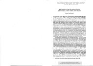
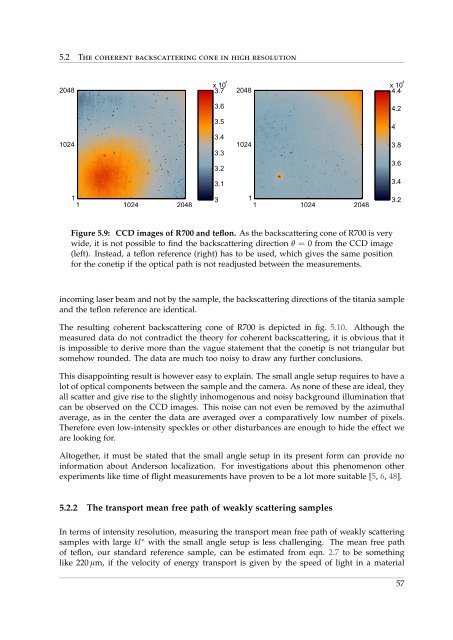
Figure 5.9: CCD images of R700 and teflon. As the backscattering cone of R700 is very<br />
wide, it is not possible to find the backscattering direction θ = 0 <strong>from</strong> the CCD image<br />
(left). Instead, a teflon reference (right) has to be used, which gives the same position<br />
for the conetip if the optical path is not readjusted between the measurements.<br />
incoming laser beam and not by the sample, the backscattering directions of the titania sample<br />
and the teflon reference are identical.<br />
The resulting coherent backscattering cone of R700 is depicted in fig. 5.10. Although the<br />
measured data do not contradict the theory for coherent backscattering, it is obvious that it<br />
is impossible to derive more than the vague statement that the conetip is not triangular but<br />
somehow rounded. The data are much too noisy to draw any further conclusions.<br />
This disappointing result is however easy to explain. The small angle setup requires to have a<br />
lot of optical components between the sample and the camera. As none of these are ideal, they<br />
all scatter and give rise to the slightly inhomogenous and noisy background illumination that<br />
can be observed on the CCD images. This noise can not even be removed by the azimuthal<br />
average, as in the center the data are averaged over a comparatively low number of pixels.<br />
Therefore even low-intensity speckles or other disturbances are enough to hide the effect we<br />
are looking for.<br />
Altogether, it must be stated that the small angle setup in its present form can provide no<br />
information about Anderson localization. For investigations about this phenomenon other<br />
experiments like time of flight measurements have proven to be a lot more suitable [5, 6, 48].<br />
5.2.2 The transport mean free path of weakly scattering samples<br />
In terms of intensity resolution, measuring the transport mean free path of weakly scattering<br />
samples with large kl ∗ with the small angle setup is less challenging. The mean free path<br />
of teflon, our standard reference sample, can be estimated <strong>from</strong> eqn. 2.7 to be something<br />
like 220 µm, if the velocity of energy transport is given by the speed of light in a material<br />
57