Coherent Backscattering from Multiple Scattering Systems - KOPS ...
Coherent Backscattering from Multiple Scattering Systems - KOPS ...
Coherent Backscattering from Multiple Scattering Systems - KOPS ...
Create successful ePaper yourself
Turn your PDF publications into a flip-book with our unique Google optimized e-Paper software.
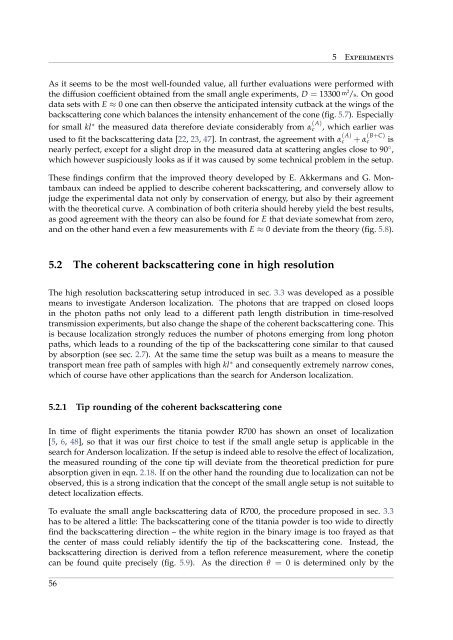
5 Experiments<br />
As it seems to be the most well-founded value, all further evaluations were performed with<br />
the diffusion coefficient obtained <strong>from</strong> the small angle experiments, D = 13300 m2 /s. On good<br />
data sets with E ≈ 0 one can then observe the anticipated intensity cutback at the wings of the<br />
backscattering cone which balances the intensity enhancement of the cone (fig. 5.7). Especially<br />
for small kl ∗ the measured data therefore deviate considerably <strong>from</strong> α (A)<br />
c , which earlier was<br />
used to fit the backscattering data [22, 23, 47]. In contrast, the agreement with α (A)<br />
c + α (B+C)<br />
c is<br />
nearly perfect, except for a slight drop in the measured data at scattering angles close to 90 ◦ ,<br />
which however suspiciously looks as if it was caused by some technical problem in the setup.<br />
These findings confirm that the improved theory developed by E. Akkermans and G. Montambaux<br />
can indeed be applied to describe coherent backscattering, and conversely allow to<br />
judge the experimental data not only by conservation of energy, but also by their agreement<br />
with the theoretical curve. A combination of both criteria should hereby yield the best results,<br />
as good agreement with the theory can also be found for E that deviate somewhat <strong>from</strong> zero,<br />
and on the other hand even a few measurements with E ≈ 0 deviate <strong>from</strong> the theory (fig. 5.8).<br />
5.2 The coherent backscattering cone in high resolution<br />
The high resolution backscattering setup introduced in sec. 3.3 was developed as a possible<br />
means to investigate Anderson localization. The photons that are trapped on closed loops<br />
in the photon paths not only lead to a different path length distribution in time-resolved<br />
transmission experiments, but also change the shape of the coherent backscattering cone. This<br />
is because localization strongly reduces the number of photons emerging <strong>from</strong> long photon<br />
paths, which leads to a rounding of the tip of the backscattering cone similar to that caused<br />
by absorption (see sec. 2.7). At the same time the setup was built as a means to measure the<br />
transport mean free path of samples with high kl ∗ and consequently extremely narrow cones,<br />
which of course have other applications than the search for Anderson localization.<br />
5.2.1 Tip rounding of the coherent backscattering cone<br />
In time of flight experiments the titania powder R700 has shown an onset of localization<br />
[5, 6, 48], so that it was our first choice to test if the small angle setup is applicable in the<br />
search for Anderson localization. If the setup is indeed able to resolve the effect of localization,<br />
the measured rounding of the cone tip will deviate <strong>from</strong> the theoretical prediction for pure<br />
absorption given in eqn. 2.18. If on the other hand the rounding due to localization can not be<br />
observed, this is a strong indication that the concept of the small angle setup is not suitable to<br />
detect localization effects.<br />
To evaluate the small angle backscattering data of R700, the procedure proposed in sec. 3.3<br />
has to be altered a little: The backscattering cone of the titania powder is too wide to directly<br />
find the backscattering direction – the white region in the binary image is too frayed as that<br />
the center of mass could reliably identify the tip of the backscattering cone. Instead, the<br />
backscattering direction is derived <strong>from</strong> a teflon reference measurement, where the conetip<br />
can be found quite precisely (fig. 5.9). As the direction θ = 0 is determined only by the<br />
56


