Coherent Backscattering from Multiple Scattering Systems - KOPS ...
Coherent Backscattering from Multiple Scattering Systems - KOPS ...
Coherent Backscattering from Multiple Scattering Systems - KOPS ...

You also want an ePaper? Increase the reach of your titles
YUMPU automatically turns print PDFs into web optimized ePapers that Google loves.
3 Setups<br />
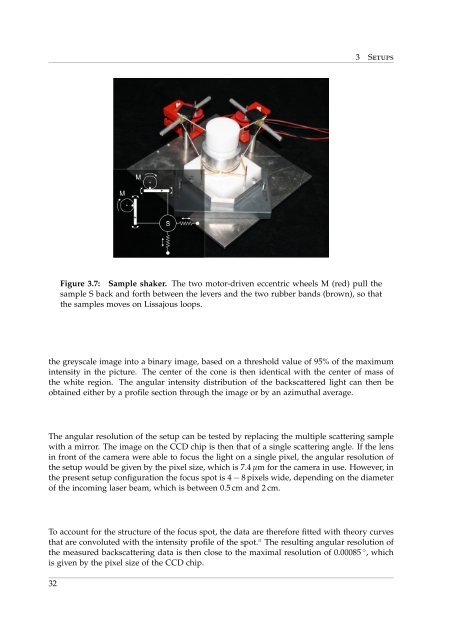
Figure 3.7: Sample shaker. The two motor-driven eccentric wheels M (red) pull the<br />
sample S back and forth between the levers and the two rubber bands (brown), so that<br />
the samples moves on Lissajous loops.<br />
the greyscale image into a binary image, based on a threshold value of 95% of the maximum<br />
intensity in the picture. The center of the cone is then identical with the center of mass of<br />
the white region. The angular intensity distribution of the backscattered light can then be<br />
obtained either by a profile section through the image or by an azimuthal average.<br />
The angular resolution of the setup can be tested by replacing the multiple scattering sample<br />
with a mirror. The image on the CCD chip is then that of a single scattering angle. If the lens<br />
in front of the camera were able to focus the light on a single pixel, the angular resolution of<br />
the setup would be given by the pixel size, which is 7.4 µm for the camera in use. However, in<br />
the present setup configuration the focus spot is 4 − 8 pixels wide, depending on the diameter<br />
of the incoming laser beam, which is between 0.5 cm and 2 cm.<br />
To account for the structure of the focus spot, the data are therefore fitted with theory curves<br />
that are convoluted with the intensity profile of the spot. a The resulting angular resolution of<br />
the measured backscattering data is then close to the maximal resolution of 0.00085 ◦ , which<br />
is given by the pixel size of the CCD chip.<br />
32