- Page 1:
VERSAMARK VL2000 Printing System VL
- Page 4 and 5:
FCC Compliance Statement This equip
- Page 6 and 7:
Scope Text Notations This manual us
- Page 9 and 10:
Contents Changes in this Version ..
- Page 11 and 12:
Contents Monitoring Operations.....
- Page 13 and 14:
Figures Figure 1 VL2000 modules....
- Page 15 and 16:
Contents Figures Figure 101 Line ho
- Page 17 and 18:
Chapter 1. Operator Controls The KO
- Page 19 and 20:
The System Controller and Its Windo
- Page 21 and 22:
The System Controller and Its Windo
- Page 23 and 24:
The System Controller and Its Windo
- Page 25 and 26:
The System Controller and Its Windo
- Page 27 and 28:
The System Controller and Its Windo
- Page 29 and 30:
Displaying Print Station Informatio
- Page 31 and 32:
Displaying Print Station Informatio
- Page 33 and 34:
Displaying Print Station Informatio
- Page 35 and 36:
Displaying Print Station Informatio
- Page 37 and 38:
Related Software IJ Data Prep Relat
- Page 39 and 40:
Related Software IJPDS Proofer IJPD
- Page 41 and 42:
Print Stations Print Stations The p
- Page 43 and 44:
Unwind Unit Unwind Unit The unwind
- Page 45 and 46:
Unwind Unit Figure 8 Unwind unit, p
- Page 47 and 48:
Unwind Unit A blue light around the
- Page 49 and 50:
Unwind Unit Drag bar A stationary b
- Page 51 and 52:
Print Tower Controls Web Guide Modu
- Page 53 and 54:
Print Tower Controls Print Tower Co
- Page 55 and 56:
Print Tower Controls Web cleaner bo
- Page 57 and 58:
Print Tower Controls Outfeed Module
- Page 59 and 60:
Rewind Unit Rewind Unit The rewind
- Page 61 and 62:
Rewind Unit External Power and Air
- Page 63 and 64:
Rewind Unit External Power and Air
- Page 65 and 66:
Chapter 2. Basic Operations Every o
- Page 67 and 68:
Operations Overview System Setup Pr
- Page 69 and 70:
Operations Overview Printhead Opera
- Page 71 and 72:
Operations Overview Printhead Opera
- Page 73 and 74:
Preliminary Operations Turning the
- Page 75 and 76:
Preliminary Operations Turning the
- Page 77 and 78:
Starting the System Controller Stan
- Page 79 and 80:
Operator Access to Controller Funct
- Page 81 and 82:
Powering the Print Station Off Powe
- Page 83 and 84:
Turning the Printing System Off Fig
- Page 85 and 86:
Turning the Printing System Off Fig
- Page 87 and 88:
Raising and Lowering the Print Towe
- Page 89 and 90:
Changing Paper Rolls at the Unwind
- Page 91 and 92:
Changing Paper Rolls at the Unwind
- Page 93 and 94:
Changing Paper Rolls at the Unwind
- Page 95 and 96:
Roll Position on the Shaft Figure 5
- Page 97 and 98:
Changing Paper Rolls at the Rewind
- Page 99 and 100:
Changing Paper Rolls at the Rewind
- Page 101 and 102:
Webbing the Unwind Unit Figure 58 W
- Page 103 and 104:
Jogging the Web Jogging the Web 1.
- Page 105 and 106:
Adjusting the Gripper Rollers Adjus
- Page 107 and 108:
Center positioning Center positioni
- Page 109 and 110:
Webbing the Web Cleaner Figure 64 W
- Page 111 and 112:
Webbing the Dryer Webbing the Dryer
- Page 113 and 114:
Webbing the Dryer Figure 67 Dryer w
- Page 115 and 116:
Webbing the Turnbar Webbing the Tur
- Page 117 and 118:
Webbing the Rewind Unit Webbing the
- Page 119 and 120:
Webbing the Rewind Unit 6. Feed eno
- Page 121 and 122:
Selecting the Motor Direction Selec
- Page 123 and 124:
Tightening the Web Use this procedu
- Page 125 and 126:
Positioning the Cue Sensor Position
- Page 127 and 128:
Printhead Activities Moving a Print
- Page 129 and 130:
Enabling an Existing Printhead Enab
- Page 131 and 132:
Setting Up Cue Mark Printing Settin
- Page 133 and 134:
Job Setup Setting Up a Print Job 5.
- Page 135 and 136:
Job Setup Setting Up a Print Job 13
- Page 137 and 138:
Job Setup Setting Up a Print Job 23
- Page 139 and 140:
Adjusting the Data Registration (Y-
- Page 141 and 142:
Adjusting the Lateral Image Positio
- Page 143 and 144:
Adjusting the Duplexed Registration
- Page 145 and 146:
Printhead Registration Printhead Re
- Page 147 and 148:
Printhead Registration VL2000 test
- Page 149 and 150:
Printhead Registration Always adjus
- Page 151 and 152:
Setting Up Page Correlation Setting
- Page 153 and 154:
Setting Up Page Correlation Setting
- Page 155 and 156:
Setting Up Page Correlation Setting
- Page 157 and 158:
Saving the Job Settings Saving the
- Page 159 and 160:
Print Operations Displaying Printhe
- Page 161 and 162:
Readying Printheads to Print Readyi
- Page 163 and 164:
Monitoring Operations • Red circl
- Page 165 and 166:
Preventing Printhead Problems Preve
- Page 167 and 168:
Print Job Operations Aligning the L
- Page 169 and 170:
Print Job Operations Aligning the L
- Page 171 and 172:
Adjusting the Dryer Temperature Adj
- Page 173 and 174:
Start Up Procedure Start Up Procedu
- Page 175 and 176:
Reprinting Data ! DANGER Stay clear
- Page 177 and 178:
Running Jobs with Job Spooling Runn
- Page 179 and 180:
Running Jobs with Job Spooling The
- Page 181 and 182:
Selecting a New Printing Speed Sele
- Page 183 and 184:
Splicing the Web Figure 85 Tear the
- Page 185 and 186:
Splicing the Web DANGER Danger of c
- Page 187 and 188:
External Fluid Container Procedure
- Page 189 and 190:
Replacing the Replenisher or Cleane
- Page 191 and 192:
Disposing of Waste Fluid Disposal G
- Page 193 and 194:
Chapter 3. Advanced Operations Only
- Page 195 and 196:
Baseline System Numbering Baseline
- Page 197 and 198:
Multiple Print Tower Numbering If n
- Page 199 and 200: Multiple Print Tower Numbering 9. S
- Page 201 and 202: Defining Print Station INet Address
- Page 203 and 204: Identifying Printheads Identifying
- Page 205 and 206: Identifying Printheads 4. Drag all
- Page 207 and 208: System Setup of Optional Functions
- Page 209 and 210: System Setup of Optional Functions
- Page 211 and 212: System Setup of Optional Functions
- Page 213 and 214: System Setup of Optional Functions
- Page 215 and 216: System Setup of Optional Functions
- Page 217 and 218: Setting Up the Activities and Users
- Page 219 and 220: Setting Up the Activities and Users
- Page 221 and 222: Setting Up the Job for Production T
- Page 223 and 224: Logging In Logging In If the CS410
- Page 225 and 226: Logging Out Logging Out While opera
- Page 227 and 228: Changing a Stop Reason Changing a S
- Page 229 and 230: How Read and Print Works How Read a
- Page 231 and 232: Positioning the Reader Positioning
- Page 233 and 234: Setting Up the Job Queue and Print
- Page 235 and 236: Setting Up the Job Queue • Keep r
- Page 237 and 238: Setting Up the Job Queue or simplex
- Page 239 and 240: Setting Up the Job Queue Figure 99
- Page 241 and 242: Using an MPC Manual Setup Making De
- Page 243 and 244: Using an MPC Manual Setup Making De
- Page 245 and 246: Using an MPC Manual Setup Overridin
- Page 247 and 248: Using an MPC Manual Setup Overridin
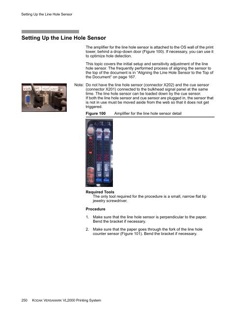
- Page 249: Using an MPC Manual Setup Overridin
- Page 253 and 254: Adjusting the Cue Sensor Adjusting
- Page 255 and 256: Setting the Cue Delays Setting the
- Page 257 and 258: Setting the Cue Delays Field Value/
- Page 259 and 260: Setting the Cue Delays f. Enter inf
- Page 261 and 262: Calculating the Speed Comp Value 1.
- Page 263 and 264: Placing the Page Correlation Marks
- Page 265 and 266: Using Special Cueing Using Special
- Page 267 and 268: Implementing Special Cueing Impleme
- Page 269 and 270: Operational Modes Entering Key Oper
- Page 271 and 272: Operational Modes Exiting Key Opera
- Page 273 and 274: Retrieving Accounting Information V
- Page 275 and 276: Replace and Packing Removing the Pr
- Page 277 and 278: Replace and Packing Removing the Pr
- Page 279 and 280: Replace and Packing Removing the Pr
- Page 281 and 282: Packing the Printhead Figure 113 Sh
- Page 283 and 284: Packing the Printhead Figure 117 Sh
- Page 285 and 286: Unpacking the Printhead Unpacking t
- Page 287 and 288: Unpacking the Printhead Figure 127
- Page 289 and 290: Installing the Printhead Figure 130
- Page 291 and 292: Installing the Printhead 16. Refer
- Page 293 and 294: Chapter 4. Maintenance In general,
- Page 295 and 296: Preventive Maintenance Table 3 Tran
- Page 297 and 298: Scheduled Operator Maintenance Proc
- Page 299 and 300: Scheduled Operator Maintenance Proc
- Page 301 and 302:
Chapter 5. Troubleshooting The erro
- Page 303 and 304:
Common Print Defects Action: Correc
- Page 305 and 306:
Printing Problems Print Screen Stat
- Page 307 and 308:
Glossary This appendix contains a g
- Page 309 and 310:
Glossary cue sensor A sensor that d
- Page 311 and 312:
Glossary 3. An architected host-to-
- Page 313 and 314:
Glossary punch-perforation A proces
- Page 315 and 316:
Glossary web break sensor A section
- Page 317 and 318:
Index Emergency Stop button unwind
- Page 319 and 320:
Index S Saving accounting informati
- Page 322:
Eastman Kodak Company 3000 Research