- Page 1 and 2:
CALIFORNIA ENERGY COMMISSION Final
- Page 3 and 4:
Acknowledgements Jim Braun and Haor
- Page 5 and 6:
Abstract Project 2.1, Fault Detecti
- Page 7 and 8:
TABLE OF CONTENTS LIST OF TABLES LI
- Page 9 and 10:
LIST OF FIGURES Page 1 - Field Test
- Page 11 and 12:
The report “Description of Labora
- Page 13 and 14:
mounted heat pumps for heating and
- Page 15 and 16:
The retail stores are in Southern C
- Page 17 and 18:
Figure 1 - Field Test Sites Data Co
- Page 19 and 20:
Gibson School (Cont’d) Woodland S
- Page 21 and 22:
Table 1 - Data List for Modular Sch
- Page 23 and 24:
BUILDING TYPE: Modular School Rooms
- Page 25 and 26:
HEATING / AIR CONDITIONING EQUIPMEN
- Page 27 and 28:
Sacramento Area McDonalds PlayPlace
- Page 29 and 30:
Bradshaw Road (Sacramento Area) McD
- Page 31 and 32:
TEST INSTRUMENTATION: Tables 2 and
- Page 33 and 34:
Table 2 - Data List for Inland Rest
- Page 35 and 36:
Table 3 - Data List for Inland Rest
- Page 37 and 38:
Table 3 - Data List for Inland Rest
- Page 39 and 40:
Castro Valley (San Francisco Bay Ar
- Page 41 and 42:
Castro Valley McDonalds PlayPlace P
- Page 43 and 44:
more or less custom design, publish
- Page 45 and 46:
BUILDING TYPE: Retail Store ADDRESS
- Page 47 and 48:
TEST INSTRUMENTATION: Similar test
- Page 49 and 50:
• Temperature and humidity levels
- Page 51 and 52:
November 2001 - December/January 20
- Page 53 and 54:
Table of Contents 1. Introduction..
- Page 55 and 56:
1. Introduction All the thermodynam
- Page 57 and 58:
Table 1.1 Comparisons of Three Mode
- Page 59 and 60:
solution procedure involves the non
- Page 61 and 62:
independent of the moisture content
- Page 63 and 64:
function, f ( X , y) , if it can be
- Page 65 and 66:
Figure 2.1 Neural-Network Implement
- Page 67 and 68:
prototype was developed by using th
- Page 69 and 70:
3. Comparison of black-box modeling
- Page 71 and 72:
which is more accurate than the exp
- Page 73 and 74:
Similar to GRNN, RBF has very good
- Page 75 and 76:
Table 3.2 RMS error (Polynomial,GRN
- Page 77 and 78:
Table 3.4 Contrast of Black-box mod
- Page 79 and 80:
Polynomial plus GRNN Training Desir
- Page 81 and 82:
interpolation(poly+GRNN) extrapolat
- Page 83 and 84:
used to build the steady-state mode
- Page 85 and 86:
α , ρ, τ I t t s h o A t a Figur
- Page 87 and 88:
Temperature (F) 82 79 76 73 Condens
- Page 89 and 90:
0.050 0.045 Pressure = 101.3 [kPa]
- Page 91 and 92:
T T − T − T W = W −W −W m =
- Page 93 and 94:
Figure 4.8 Output of three steady-s
- Page 95 and 96:
will be calculated to represent the
- Page 97 and 98:
180 175 RMS error = 0.3984 (F) Pred
- Page 99 and 100:
180 175 RMS error =1.1472 (F) Predi
- Page 101 and 102:
51 50 RMS error=0.3860 (F) Predicte
- Page 103 and 104:
4.4 California field site results S
- Page 105 and 106: 105 100 RMS error =0.5982 (F) Predi
- Page 107 and 108: Since air conditioners always cycle
- Page 109 and 110: 6. Conclusions and future work So f
- Page 111 and 112: Lee, W., House, J.M. and Shin, D.R.
- Page 113 and 114: Table of Contents 1 Introduction...
- Page 115 and 116: AHU α β 2 d i EER ∆ ∆ η v T
- Page 117 and 118: $ !! !! )
- Page 119 and 120: Paper statistics in HVAC FDD Number
- Page 121 and 122: 011>" - , ?" 8?"
- Page 123 and 124: + : 6336" ,
- Page 125 and 126: + :: !!- :: !!
- Page 127 and 128: 6 24 122 7) 6 3++, ) . !! /011
- Page 129 and 130: )
- Page 131 and 132: 336 F / s $ S
- Page 133 and 134: N $ V v1
- Page 135 and 136: Figure 3-4 2-dimensional residual d
- Page 137 and 138: 10 5 Normal and current operation p
- Page 139 and 140: 7 N Ω f N N Ω = Ω X ,
- Page 141 and 142: 0 + α 6 d χ ( )
- Page 143 and 144: Normal operation region Residual-2
- Page 145 and 146: Table 3-2 Refrigerant Leak at 20% l
- Page 147 and 148: ratio dist = P F 1 P F 1 2 1 9.0
- Page 149 and 150: $ , " - (
- Page 151 and 152: )(( 0( 04 ) 6330" /
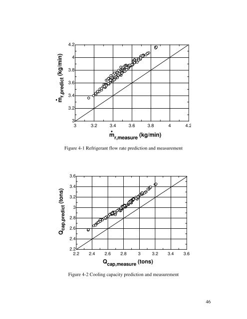
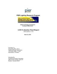
- Page 153: Table 4-2 Polynomial plus GRNN mode
- Page 158 and 159: 3.6 3.4 w predict (kw) 3.2 3 2.8 2.
- Page 160 and 161: ) M normal Σ normal .
- Page 162 and 163: 62? "J032 "J08< "J96< "J? 6"J90 &"J
- Page 164 and 165: Table 4-13 Average (right, wrong) f
- Page 166 and 167: ) c !! c ,63 0 )
- Page 168 and 169: ) "
- Page 170 and 171: # ASHRAE. 1993. ASHRAE Handbook -
- Page 172 and 173: Glass, A.Sl, Gruber, P.,Roos, and M
- Page 174 and 175: .44(' 238 )!;( ( ; :;) ) !!
- Page 176 and 177: $ * 8(! 0( + .
- Page 178 and 179: $ ) / $$
- Page 180 and 181: Table 3 Sensitivity of Statistical
- Page 182 and 183: n 2 yi di 2 2 + d x = ( − ) ~ χ
- Page 184 and 185: Load 20% 40% 60% 80% 100% 3 4 Fault
- Page 186 and 187: Load 20% 40% 60% 80% 100% 3 4 Fault
- Page 188 and 189: PF = ( x − c) + ( y − c) PF (
- Page 190 and 191: , % $ ) ?
- Page 192 and 193: A DECOUPLING-BASED FDD APPROACH FOR
- Page 194 and 195: 3 1.2.3.4 Evaporator Fouling Fault
- Page 196 and 197: 5 LIST OF FIGURES Figure 1-1 System
- Page 198 and 199: 7 Figure A2-1 RTD measuring scheme
- Page 200 and 201: 9 NOMENCLATURE AHU α α β c = Air
- Page 202 and 203: 11 ABSTRACT Although the statistica
- Page 204 and 205: 13 1 THE FAULT DETECTION AND DIAGNO
- Page 206 and 207:
15 So, the input-output relationshi
- Page 208 and 209:
17 As a result of these considerati
- Page 210 and 211:
19 1.1.2 Fault Diagnosis Fault diag
- Page 212 and 213:
21 ⎛ ⎡n⎤⎞ ⎜ ⎢ ⎥⎟
- Page 214 and 215:
23 or pattern are coordinate axes,
- Page 216 and 217:
25 To eliminate impacts of the line
- Page 218 and 219:
27 faults’ features ( j ≠ i z j
- Page 220 and 221:
29 while classical thermodynamics f
- Page 222 and 223:
31 condenser air flow rate results
- Page 224 and 225:
33 To handle multiple-simultaneous
- Page 226 and 227:
35 When a compressor valve has leak
- Page 228 and 229:
37 L 2 1 P cond = Pdis − 0 ( fvdx
- Page 230 and 231:
39 rncg o ∆ Tcond, abnorm < −34
- Page 232 and 233:
41 Also, high velocity air makes it
- Page 234 and 235:
43 Figure 1-9 illustrates the liqui
- Page 236 and 237:
45 is extremely low. However, it is
- Page 238 and 239:
47 & corresponding to the speed set
- Page 240 and 241:
49 NonCond CondFoul CompLeak EvapFo
- Page 242 and 243:
51 The penalty of using this low-co
- Page 244 and 245:
53 2 CASE STUDIES In order to valid
- Page 246 and 247:
55 2.1.2 Condenser Fouling Decoupli
- Page 248 and 249:
57 point the actual evaporator air
- Page 250 and 251:
59 Liquid-Line Pressure Drop (psi)
- Page 252 and 253:
61 30 refleak compleak llrestr cond
- Page 254 and 255:
63 Refrigerant Low-charge Refrigera
- Page 256 and 257:
65 Although the predefined fault le
- Page 258 and 259:
67 Figure 2-13 Outputs of the FDD d
- Page 260 and 261:
69 Although every individual fault
- Page 262 and 263:
71 FDDRW), FDDRW recommended that:
- Page 264 and 265:
73 Figure 2-19 Outputs of the FDD d
- Page 266 and 267:
75 2.3 Results for California Field
- Page 268 and 269:
77 Figure 2-23 plots the normalized
- Page 270 and 271:
79 Figure 2-25 Histogram bar plot o
- Page 272 and 273:
81 Figure 2-28 Histogram bar plot o
- Page 274 and 275:
83 Faults Refrigerant Charge Liquid
- Page 276 and 277:
85 REFERENCE Aaron, D. A., and P. A
- Page 278 and 279:
87 Dexter, Arthur; Pakanen, Jouko (
- Page 280 and 281:
89 Journal of Heating, Ventilating,
- Page 282 and 283:
91 devices. An equation for liquid
- Page 284 and 285:
93 application falls into the “ve
- Page 286 and 287:
95 6.84 Tevap=40F Tevap=20F Tevap=0
- Page 288 and 289:
97 In summary, from manufacturers
- Page 290 and 291:
99 Figure A1-7 shows the geometric
- Page 292 and 293:
101 Figure A1-9 shows the refrigera
- Page 294 and 295:
103 Table A1-1 TXV rating settings
- Page 296 and 297:
105 Assuming the reserve capacity i
- Page 298 and 299:
107 Relative error of mass flow rat
- Page 300 and 301:
109 APPENDIX 2 RTD TEMPERATURE SENS
- Page 302 and 303:
111 Table A2-1 Thermal resistance d
- Page 304 and 305:
1 AUTOMATED FAULT DETECTION AND DIA
- Page 306 and 307:
2 TABLE OF CONTENTS ACKNOWLEDGEMENT
- Page 308 and 309:
4 5 ECONOMIC ASSESSMENTS ..........
- Page 310 and 311:
Figure 4-17 Outputs of the FDD demo
- Page 312 and 313:
8 NOMENCLATURE ANN = Artificial neu
- Page 314 and 315:
10 σ = Standard deviation σ norma
- Page 316 and 317:
12 normal state variables, 2) stead
- Page 318 and 319:
14 Figure E-2 Histogram of the norm
- Page 320 and 321:
16 Faults Refrigerant Charge Liquid
- Page 322 and 323:
18 3. Elimination of preventative m
- Page 324 and 325:
20 1 INTRODUCTION 1.1 Background on
- Page 326 and 327:
22 In order to reduce hardware cost
- Page 328 and 329:
24 1.2.2 Latest Progress Since 1999
- Page 330 and 331:
26 class of high cost fault, accoun
- Page 332 and 333:
28 motor speed. This technique was
- Page 334 and 335:
30 faults, which requires tremendou
- Page 336 and 337:
32 2. Existing techniques for onlin
- Page 338 and 339:
34 interactions among multiple fact
- Page 340 and 341:
36 2.2.1.1 Normal Operation Data Th
- Page 342 and 343:
38 charge faults for TXV RTU system
- Page 344 and 345:
40 3 IMPROVED SRB FDD METHOD As dep
- Page 346 and 347:
42 3.2 Improved SRB Approach Figure
- Page 348 and 349:
44 model has better performance in
- Page 350 and 351:
46 Fault type Table 3-1 Fault diagn
- Page 352 and 353:
48 3.3 Results Table 3-2 gives comp
- Page 354 and 355:
50 In order to extend the easily-im
- Page 356 and 357:
52 The characteristic of component-
- Page 358 and 359:
54 4.2 Results In order to validate
- Page 360 and 361:
56 Condenser Air Mass Flow Rate (lb
- Page 362 and 363:
58 Evaporator Air Mass Flow Rate (l
- Page 364 and 365:
60 4.2.1.4 Liquid-Line Restriction
- Page 366 and 367:
62 4.2.1.5 Refrigerant Leakage Deco
- Page 368 and 369:
64 4.2.2.1 Field Fault Simulation W
- Page 370 and 371:
66 4.2.2.2 Fault Detection and Diag
- Page 372 and 373:
68 4.2.2.5 Output of the FDD Demons
- Page 374 and 375:
70 simultaneous faults: refrigerant
- Page 376 and 377:
72 Figure 4-19 shows one frame afte
- Page 378 and 379:
74 charge with the fault severity o
- Page 380 and 381:
76 4.2.3 Results for California Fie
- Page 382 and 383:
78 Figure 4-25 plots the normalized
- Page 384 and 385:
80 Figure 4-27 Histogram bar plot o
- Page 386 and 387:
82 Figure 4-30 Histogram bar plot o
- Page 388 and 389:
84 Faults Refrigerant Charge Liquid
- Page 390 and 391:
86 perform emergency service when a
- Page 392 and 393:
88 5.2.1 Utility Cost Savings (UCS)
- Page 394 and 395:
90 where β is a degradation factor
- Page 396 and 397:
92 2. The savings are greatest for
- Page 398 and 399:
94 performance is realized. Accordi
- Page 400 and 401:
96 1. Planned preventive maintenanc
- Page 402 and 403:
98 Table 5-6 Equipment Lifetime Ope
- Page 404 and 405:
100 6 SUMMARY AND RECOMMENDATIONS F
- Page 406 and 407:
102 5. Conduct more field tests und
- Page 408 and 409:
104 Breuker, M.S., 1997a. Evaluatio
- Page 410 and 411:
106 Isermann, R. 1984. Process Faul