Fault Detection and Diagnostics for Rooftop Air Conditioners
Fault Detection and Diagnostics for Rooftop Air Conditioners
Fault Detection and Diagnostics for Rooftop Air Conditioners
Create successful ePaper yourself
Turn your PDF publications into a flip-book with our unique Google optimized e-Paper software.
6<br />
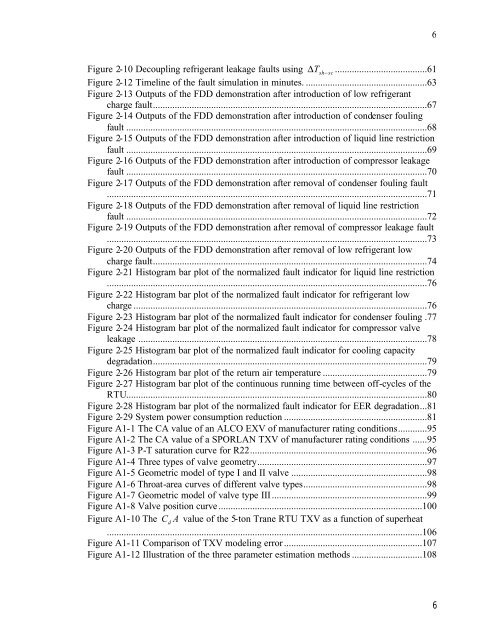
Figure 2-10 Decoupling refrigerant leakage faults using ∆ Tsh<br />
− sc......................................61<br />
Figure 2-12 Timeline of the fault simulation in minutes. ..................................................63<br />
Figure 2-13 Outputs of the FDD demonstration after introduction of low refrigerant<br />
charge fault.................................................................................................................67<br />
Figure 2-14 Outputs of the FDD demonstration after introduction of condenser fouling<br />
fault ............................................................................................................................68<br />
Figure 2-15 Outputs of the FDD demonstration after introduction of liquid line restriction<br />
fault ............................................................................................................................69<br />
Figure 2-16 Outputs of the FDD demonstration after introduction of compressor leakage<br />
fault ............................................................................................................................70<br />
Figure 2-17 Outputs of the FDD demonstration after removal of condenser fouling fault<br />
....................................................................................................................................71<br />
Figure 2-18 Outputs of the FDD demonstration after removal of liquid line restriction<br />
fault ............................................................................................................................72<br />
Figure 2-19 Outputs of the FDD demonstration after removal of compressor leakage fault<br />
....................................................................................................................................73<br />
Figure 2-20 Outputs of the FDD demonstration after removal of low refrigerant low<br />
charge fault.................................................................................................................74<br />
Figure 2-21 Histogram bar plot of the normalized fault indicator <strong>for</strong> liquid line restriction<br />
....................................................................................................................................76<br />
Figure 2-22 Histogram bar plot of the normalized fault indicator <strong>for</strong> refrigerant low<br />
charge .........................................................................................................................76<br />
Figure 2-23 Histogram bar plot of the normalized fault indicator <strong>for</strong> condenser fouling .77<br />
Figure 2-24 Histogram bar plot of the normalized fault indicator <strong>for</strong> compressor valve<br />
leakage .......................................................................................................................78<br />
Figure 2-25 Histogram bar plot of the normalized fault indicator <strong>for</strong> cooling capacity<br />
degradation.................................................................................................................79<br />
Figure 2-26 Histogram bar plot of the return air temperature ...........................................79<br />
Figure 2-27 Histogram bar plot of the continuous running time between off-cycles of the<br />
RTU............................................................................................................................80<br />
Figure 2-28 Histogram bar plot of the normalized fault indicator <strong>for</strong> EER degradation...81<br />
Figure 2-29 System power consumption reduction ...........................................................81<br />
Figure A1-1 The CA value of an ALCO EXV of manufacturer rating conditions............95<br />
Figure A1-2 The CA value of a SPORLAN TXV of manufacturer rating conditions ......95<br />
Figure A1-3 P-T saturation curve <strong>for</strong> R22.........................................................................96<br />
Figure A1-4 Three types of valve geometry......................................................................97<br />
Figure A1-5 Geometric model of type I <strong>and</strong> II valve ........................................................98<br />
Figure A1-6 Throat-area curves of different valve types...................................................98<br />
Figure A1-7 Geometric model of valve type III................................................................99<br />
Figure A1-8 Valve position curve....................................................................................100<br />
Figure A1-10 The C d<br />
A value of the 5-ton Trane RTU TXV as a function of superheat<br />
..................................................................................................................................106<br />
Figure A1-11 Comparison of TXV modeling error.........................................................107<br />
Figure A1-12 Illustration of the three parameter estimation methods .............................108<br />
6


