SPECIFICATION FOR THE DESIGN OF - Transcon Steel
SPECIFICATION FOR THE DESIGN OF - Transcon Steel
SPECIFICATION FOR THE DESIGN OF - Transcon Steel

Create successful ePaper yourself
Turn your PDF publications into a flip-book with our unique Google optimized e-Paper software.
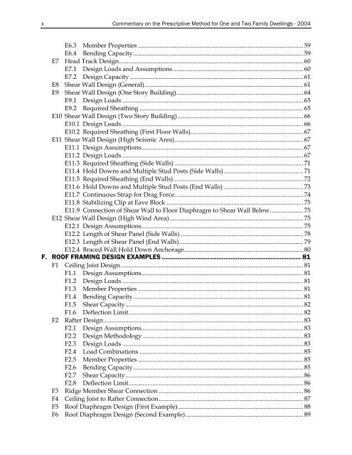
x Commentary on the Prescriptive Method for One and Two Family Dwellings - 2004<br />
E6.3 Member Properties ........................................................................................................ 59<br />
E6.4 Bending Capacity........................................................................................................... 59<br />
E7 Head Track Design.................................................................................................................... 60<br />
E7.1 Design Loads and Assumptions .................................................................................. 60<br />
E7.2 Design Capacity ............................................................................................................. 61<br />
E8 Shear Wall Design (General).................................................................................................... 61<br />
E9 Shear Wall Design (One Story Building)................................................................................ 64<br />
E9.1 Design Loads .................................................................................................................. 65<br />
E9.2 Required Sheathing ....................................................................................................... 65<br />
E10 Shear Wall Design (Two Story Building)............................................................................... 66<br />
E10.1 Design Loads .................................................................................................................. 66<br />
E10.2 Required Sheathing (First Floor Walls)....................................................................... 67<br />
E11 Shear Wall Design (High Seismic Area)................................................................................. 67<br />
E11.1 Design Assumptions...................................................................................................... 67<br />
E11.2 Design Loads .................................................................................................................. 67<br />
E11.3 Required Sheathing (Side Walls) ................................................................................. 71<br />
E11.4 Hold Downs and Multiple Stud Posts (Side Walls).................................................. 71<br />
E11.5 Required Sheathing (End Walls).................................................................................. 72<br />
E11.6 Hold Downs and Multiple Stud Posts (End Walls) .................................................. 73<br />
E11.7 Continuous Strap for Drag Force................................................................................. 74<br />
E11.8 Stabilizing Clip at Eave Block ...................................................................................... 75<br />
E11.9 Connection of Shear Wall to Floor Diaphragm to Shear Wall Below..................... 75<br />
E12 Shear Wall Design (High Wind Area) .................................................................................... 75<br />
E12.1 Design Assumptions...................................................................................................... 75<br />
E12.2 Length of Shear Panel (Side Walls) ............................................................................. 78<br />
E12.3 Length of Shear Panel (End Walls).............................................................................. 79<br />
E12.4 Braced Wall Hold Down Anchorage........................................................................... 80<br />
F. RO<strong>OF</strong> FRAMING <strong>DESIGN</strong> EXAMPLES ............................................................................... 81<br />
F1 Ceiling Joist Design................................................................................................................... 81<br />
F1.1 Design Assumptions...................................................................................................... 81<br />
F1.2 Design Loads .................................................................................................................. 81<br />
F1.3 Member Properties ........................................................................................................ 81<br />
F1.4 Bending Capacity........................................................................................................... 81<br />
F1.5 Shear Capacity................................................................................................................ 82<br />
F1.6 Deflection Limit.............................................................................................................. 82<br />
F2 Rafter Design.............................................................................................................................. 83<br />
F2.1 Design Assumptions...................................................................................................... 83<br />
F2.2 Design Methodology ..................................................................................................... 83<br />
F2.3 Design Loads .................................................................................................................. 83<br />
F2.4 Load Combinations ....................................................................................................... 85<br />
F2.5 Member Properties ........................................................................................................ 85<br />
F2.6 Bending Capacity........................................................................................................... 85<br />
F2.7 Shear Capacity................................................................................................................ 86<br />
F2.8 Deflection Limit.............................................................................................................. 86<br />
F3 Ridge Member Shear Connection ........................................................................................... 86<br />
F4 Ceiling Joist to Rafter Connection........................................................................................... 87<br />
F5 Roof Diaphragm Design (First Example)............................................................................... 88<br />
F6 Roof Diaphragm Design (Second Example).......................................................................... 89