SPECIFICATION FOR THE DESIGN OF - Transcon Steel
SPECIFICATION FOR THE DESIGN OF - Transcon Steel
SPECIFICATION FOR THE DESIGN OF - Transcon Steel

Create successful ePaper yourself
Turn your PDF publications into a flip-book with our unique Google optimized e-Paper software.
Commentary on the Prescriptive Method for One and Two Family Dwellings - 2004 75<br />
V n = 3,388 lb<br />
V a = V n /Ω = 3,388/1.67 = 2,029 lb<br />
ΦV n = 0.90(3,388) = 3,049 lb<br />
Clip Spacing = 3,049/346 = 8.81 feet<br />
Space blocking at 8-foot maximum and at each end.<br />
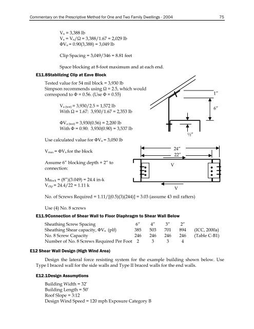
E11.8 Stabilizing Clip at Eave Block<br />
Tested value for 54 mil block = 3,930 lb<br />
Simpson recommends using Ω = 2.5, which would<br />
correspond to Φ = 0.56. (Use Φ = 0.55) 1”<br />
V a (test) = 3,930/2.5 = 1,572 lb<br />
With Ω = 1.67: 3,930/1.67 = 2,353 lb<br />
6”<br />
ΦV a (test) = 3,930(0.56) = 2,200 lb<br />
With Φ = 0.90: 3,930(0.90) = 3,537 lb<br />
Use calculated value for ΦV n = 3,050 lb<br />
½”<br />
V max = ΦV n for the block<br />
Assume 6” blocking depth + 2” to<br />
connection:<br />
V<br />
24”<br />
22”<br />
M Block = (8”)(3.049) = 24.4 in-k<br />
V clip = 24.4/22 = 1.11 k<br />
No. of Screws Required = 1.11/[(0.5)(3)(244)] = 3.03 (assume 43 mil rafters)<br />
Use (4) No. 8 screws<br />
E11.9 Connection of Shear Wall to Floor Diaphragm to Shear Wall Below<br />
Sheathing Screw Spacing 6” 4” 3” 2”<br />
Sheathing Shear capacity, ΦV n (plf) 385 503 701 894 (ICC, 2000a)<br />
No. 8 Screw Capacity 246 246 246 246 (Table C-B1)<br />
Number of No. 8 Screws Required Per Foot 2 3 3 4<br />
E12 Shear Wall Design (High Wind Area)<br />
Design the lateral force resisting system for the example building shown below. Use<br />
Type I braced wall for the side walls and Type II braced walls for the end walls.<br />
E12.1 Design Assumptions<br />
Building Width = 32’<br />
Building Length = 50’<br />
Roof Slope = 3:12<br />
Design Wind Speed = 120 mph Exposure Category B<br />
V