SPECIFICATION FOR THE DESIGN OF - Transcon Steel
SPECIFICATION FOR THE DESIGN OF - Transcon Steel
SPECIFICATION FOR THE DESIGN OF - Transcon Steel

Create successful ePaper yourself
Turn your PDF publications into a flip-book with our unique Google optimized e-Paper software.
30 Commentary on the Prescriptive Method for One and Two Family Dwellings - 2004<br />
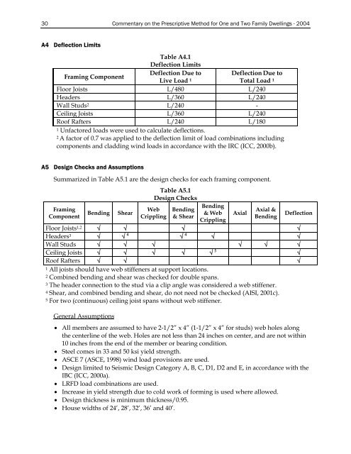
A4 Deflection Limits<br />
Table A4.1<br />
Deflection Limits<br />
Framing Component<br />
Deflection Due to Deflection Due to<br />
Live Load 1<br />
Total Load 1<br />
Floor Joists L/480 L/240<br />
Headers L/360 L/240<br />
Wall Studs 2 L/240 -<br />
Ceiling Joists L/360 L/240<br />
Roof Rafters L/240 L/180<br />
1 Unfactored loads were used to calculate deflections.<br />
2 A factor of 0.7 was applied to the deflection limit of load combinations including<br />
components and cladding wind loads in accordance with the IRC (ICC, 2000b).<br />
A5 Design Checks and Assumptions<br />
Summarized in Table A5.1 are the design checks for each framing component.<br />
Framing<br />
Component<br />
Bending<br />
Shear<br />
Table A5.1<br />
Design Checks<br />
Web<br />
Crippling<br />
Bending<br />
& Shear<br />
Bending<br />
& Web<br />
Crippling<br />
Axial<br />
Axial &<br />
Bending<br />
Deflection<br />
Floor Joists 1,2 √ √ √ √<br />
Headers 3 √ √ 4 √ 4 √ √<br />
Wall Studs √ √ √ √ √ √<br />
Ceiling Joists √ √ √ √ √ 5 √<br />
Roof Rafters √ √ √<br />
1 All joists should have web stiffeners at support locations.<br />
2 Combined bending and shear was checked for double spans.<br />
3 The header connection to the stud via a clip angle was considered a web stiffener.<br />
4 Shear, and combined bending and shear, do not need not be checked (AISI, 2001c).<br />
5 For two (continuous) ceiling joist spans without web stiffener.<br />
General Assumptions<br />
• All members are assumed to have 2-1/2” x 4” (1-1/2” x 4” for studs) web holes along<br />
the centerline of the web. Holes are not less than 24 inches on center, and are not within<br />
10 inches from the end of the member or bearing condition.<br />
• <strong>Steel</strong> comes in 33 and 50 ksi yield strength.<br />
• ASCE 7 (ASCE, 1998) wind load provisions are used.<br />
• Design limited to Seismic Design Category A, B, C, D1, D2 and E, in accordance with the<br />
IBC (ICC, 2000a).<br />
• LRFD load combinations are used.<br />
• Increase in yield strength due to cold work of forming is used where allowed.<br />
• Design thickness is minimum thickness/0.95.<br />
• House widths of 24’, 28’, 32’, 36’ and 40’.