SPECIFICATION FOR THE DESIGN OF - Transcon Steel
SPECIFICATION FOR THE DESIGN OF - Transcon Steel
SPECIFICATION FOR THE DESIGN OF - Transcon Steel

Create successful ePaper yourself
Turn your PDF publications into a flip-book with our unique Google optimized e-Paper software.
70 Commentary on the Prescriptive Method for One and Two Family Dwellings - 2004<br />
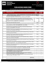
Diaphragm Loads 50’<br />
W px2<br />
F px =<br />
n<br />
∑<br />
i=<br />
x<br />
n<br />
∑<br />
i=<br />
x<br />
F<br />
W<br />
x<br />
i<br />
W<br />
px<br />
30’<br />
W px1<br />
V px2<br />
V px2<br />
V px1<br />
V px1<br />
Diaphragm<br />
F x W x<br />
(lb) (lb)<br />
Roof 9,638 36,330<br />
2 nd Floor 3,799 32,580<br />
W px<br />
ΣF i<br />
ΣW i<br />
F px V px<br />
(lb)<br />
(lb)<br />
(lb) (lb) (lb/ft)<br />
W px1 =34,440 9,638 36,330 9,137 152<br />
W px2 =33,180<br />
8,802 88<br />
W px1 =28,800 13,437 68,910 5,616 94<br />
W px2 =26,280<br />
5,124 51<br />
Compare with 0.15(S DS I E W px ) and 0.3 (S DS I E W px ) (IBC Eq. 1620.3.3)<br />
S DS = 1.17; I E = 1.0<br />
0.15(S DS I E W px ) 0.3 (S DS I E W px )<br />
Roof 6,044 lb < 9,137 lb < 12,088 lb ok<br />
2 nd 5,054 lb < 5,616 lb < 10,109 lb ok<br />
Diaphragm Chord Splice Requirements<br />
Determine Chord Force and Splice Requirements with Amplified Chord Force<br />
Diaphragm<br />
W p<br />
(lb/ft)<br />
L<br />
(ft)<br />
C=T (lb) Ω 0 Ω 0 T Required No. 8<br />
Screws @ Splice<br />
Roof 183 50 1,906 2.5 4,765 20<br />
293 30 659<br />
1,648 7<br />
2 nd Floor 113 50 1,177 2.5 2,943 12<br />
W p = F px /L; C=T= W p L 2 /8L 2<br />
171 30 385<br />
963 4<br />
Note: Ω 0 = 2.5 based on system 1.K from Table 1617.6 of the IBC 2000 with 0.5<br />
reduction for flexible diaphragm (3.0 – 0.5 = 2.5)<br />
Note: For No. 8 screws, assuming 33 mil top track:<br />
Φ = 0.5 for screws in shear<br />
V n = 492 lb<br />
Φ V n = 246 lb