SPECIFICATION FOR THE DESIGN OF - Transcon Steel
SPECIFICATION FOR THE DESIGN OF - Transcon Steel
SPECIFICATION FOR THE DESIGN OF - Transcon Steel

Create successful ePaper yourself
Turn your PDF publications into a flip-book with our unique Google optimized e-Paper software.
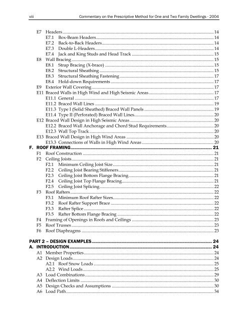
viii Commentary on the Prescriptive Method for One and Two Family Dwellings - 2004<br />
E7 Headers....................................................................................................................................... 14<br />
E7.1 Box-Beam Headers......................................................................................................... 14<br />
E7.2 Back-to-Back Headers.................................................................................................... 14<br />
E7.3 Double L-Headers.......................................................................................................... 14<br />
E7.4 Jack and King Studs and Head Track ......................................................................... 15<br />
E8 Wall Bracing............................................................................................................................... 15<br />
E8.1 Strap Bracing (X-brace) ................................................................................................. 15<br />
E8.2 Structural Sheathing ...................................................................................................... 15<br />
E8.3 Structural Sheathing Fastening .................................................................................... 17<br />
E8.4 Hold-down Requirements ............................................................................................ 17<br />
E9 Exterior Wall Covering............................................................................................................. 17<br />
E11 Braced Walls in High Wind and High Seismic Areas.......................................................... 17<br />
E11.1 General ............................................................................................................................ 17<br />
E11.2 Braced Wall Lines .......................................................................................................... 19<br />
E11.3 Type I (Solid Sheathed) Braced Wall Panels .............................................................. 19<br />
E11.4 Type II (Perforated) Braced Wall Lines....................................................................... 20<br />
E12 Braced Wall Design in High Seismic Areas........................................................................... 20<br />
E12.2 Braced Wall Anchorage and Chord Stud Requirements.......................................... 20<br />
E12.3 Wall Top Track ............................................................................................................... 20<br />
E13 Braced Wall Design in High Wind Areas .............................................................................. 20<br />
E13.3 Connections of Walls in High Wind Areas ................................................................ 20<br />
F. RO<strong>OF</strong> FRAMING.................................................................................................................. 21<br />
F1 Roof Construction ..................................................................................................................... 21<br />
F2 Ceiling Joists............................................................................................................................... 21<br />
F2.1 Minimum Ceiling Joist Size.......................................................................................... 21<br />
F2.2 Ceiling Joist Bearing Stiffeners..................................................................................... 21<br />
F2.3 Ceiling Joist Bottom Flange Bracing............................................................................ 21<br />
F2.4 Ceiling Joist Top Flange Bracing.................................................................................. 21<br />
F2.5 Ceiling Joist Splicing...................................................................................................... 22<br />
F3 Roof Rafters................................................................................................................................22<br />
F3.1 Minimum Roof Rafter Sizes.......................................................................................... 22<br />
F3.2 Roof Rafter Support Brace ............................................................................................ 22<br />
F3.3 Rafter Splice .................................................................................................................... 22<br />
F3.5 Rafter Bottom Flange Bracing ...................................................................................... 22<br />
F4 Framing of Openings in Roofs and Ceilings ......................................................................... 23<br />
F5 Roof Trusses ............................................................................................................................... 23<br />
F6 Roof Diaphragms ...................................................................................................................... 23<br />
PART 2 – <strong>DESIGN</strong> EXAMPLES................................................................................................. 24<br />
A. INTRODUCTION................................................................................................................... 24<br />
A1 Member Properties.................................................................................................................... 24<br />
A2 Design Loads.............................................................................................................................. 24<br />
A2.1 Roof Snow Loads ........................................................................................................... 25<br />
A2.2 Wind Loads..................................................................................................................... 25<br />
A3 Load Combinations................................................................................................................... 29<br />
A4 Deflection Limits ....................................................................................................................... 30<br />
A5 Design Checks and Assumptions ........................................................................................... 30<br />
A6 Load Path.................................................................................................................................... 34