PDFï¼7.7MB
PDFï¼7.7MB
PDFï¼7.7MB

You also want an ePaper? Increase the reach of your titles
YUMPU automatically turns print PDFs into web optimized ePapers that Google loves.
EXH<br />
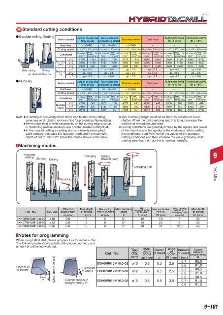
Standard cutting conditions<br />
Shoulder milling, Slotting<br />
ap<br />
9<br />
H1<br />
ap<br />
Side cutting Slotting<br />
ap: Axial depth of cut<br />
Plunging<br />
Work material<br />
Hardness<br />
Cutting speed<br />
Conditions<br />
Tool dia.<br />
(mm)<br />
Depth of<br />
cut<br />
ø10<br />
ø12<br />
ø16<br />
ø10<br />
ø12<br />
ø16<br />
Work material<br />
Hardness<br />
Cutting speed<br />
Conditions<br />
Tool dia.<br />
(mm)<br />
ø10<br />
ø12<br />
ø16<br />
Carbon steels and Alloy steels and<br />
Stainless steels<br />
alloy steels prehardened steelst<br />
Cast irons<br />
Aluminium alloys<br />
(Si < 13%)<br />
Aluminium alloys<br />
(Si 13%)<br />
< 30HRC 30 ~ 40HRC < 250HB - - -<br />
Vc = 100 ~ 300 m/min Vc = 100 ~ 250 m/min Vc = 100 ~ 300 m/min Vc = 100 ~ 300 m/min Vc = 100 ~ 500 m/min Vc = 100 ~ 300 m/min<br />
No. of rev. n<br />
Feed vf No. of rev. n<br />
Feed vf No. of rev. n<br />
Feed vf No. of rev. n<br />
Feed vf No. of rev. n<br />
Feed vf No. of rev. n<br />
Feed<br />
min -1 speed<br />
mm/min min -1 speed<br />
mm/min min -1 speed<br />
mm/min min -1 speed<br />
mm/min min -1 speed<br />
mm/min min -1 speed vf<br />
mm/min<br />
4770 1430 3820 760 4770 1430 6360 2540 9550 5730 6360 3180<br />
3980 1190 3180 630 3980 1190 5300 2120 7950 4770 5300 2650<br />
2980 890 2380 470 2980 890 3970 1580 5960 3570 3970 1980<br />
ap < 0.6 ap < 0.5 ap < 0.6 ap < 0.6 ap < 0.6 ap < 0.6<br />
ae < 0.6 ae < 0.5 ae < 0.6 ae < 0.6 ae < 0.6 ae < 0.6<br />
ap < 0.8 ap < 0.6 ap < 0.8 ap < 0.8 ap < 0.8 ap < 0.8<br />
Carbon steels and Alloy steels and<br />
Stainless steels<br />
alloy steels prehardened steelst<br />
Cast irons<br />
Aluminium alloys<br />
(Si < 13%)<br />
Aluminium alloys<br />
(Si 13%)<br />
< 30HRC 30 ~ 40HRC < 250HB - - -<br />
Vc = 100 ~ 300 m/min Vc = 100 ~ 250 m/min Vc = 100 ~ 300 m/min Vc = 100 ~ 300 m/min Vc = 100 ~ 500 m/min Vc = 100 ~ 300 m/min<br />
No. of rev. n<br />
Feed vf No. of rev. n<br />
Feed vf No. of rev. n<br />
Feed vf No. of rev. n<br />
Feed vf No. of rev. n<br />
Feed vf No. of rev. n<br />
Feed<br />
min -1 speed<br />
mm/min min -1 speed<br />
mm/min min -1 speed<br />
mm/min min -1 speed<br />
mm/min min -1 speed<br />
mm/min min -1 speed vf<br />
mm/min<br />
4770 240 3820 150 4770 240 6360 440 9550 760 6360 440<br />
3980 200 3180 130 3980 200 5300 370 7950 640 5300 370<br />
2980 150 2380 95 2980 150 3970 280 5960 480 3970 280<br />
Note:¡In slotting or pocketing where chips tend to stay in the cutting<br />
zone, use an air blast to remove chips for preventing chip recutting.<br />
¡When chips tend to weld excessively on the cutting edge such as<br />
in machining aluminium alloys, use a water soluble cutting fluid.<br />
¡In the case of cutting a casting skin or a heavily interrupted<br />
work surface, decrease the feed per tooth and the maximum<br />
depth of cut to 1/2 to 2/3 times the values shown in the table.<br />
Machining modes<br />
Shoulder<br />
milling<br />
Plunging<br />
Slotting Drilling<br />
Drilling<br />
(Helical feed)<br />
¡Tool overhang length must be as short as possible to avoid<br />
chatter. When the tool overhang length is long, decrease the<br />
number of revolutions and feed.<br />
¡Cutting conditions are generally limited by the rigidity and power<br />
of the machine and the rigidity of the workpiece. When setting<br />
the conditions, start from half of the values of the standard<br />
cutting conditions and then increase the value gradually whilst<br />
making sure that the machine is running normally.<br />
Ramping<br />
Enlarging hole<br />
TAC Mills<br />
H<br />
ae<br />
ap<br />
ap<br />
W<br />
D1, D2<br />
Effective Max.depth Max. cutting Max. ramping Min. Max. machinable Max. cutting Max.depth<br />
Cat. No. Tool dia. edge length of drilling width in plunging<br />
machinable<br />
angle hole dia. hole dia.<br />
width in<br />
enlarging hole of boring<br />
ap (mm) H (mm) W (mm) θ D1 (mm) D2 (mm) ae (mm) H1 (mm)<br />
EXH06R010M10.0-02 ø10 0.6 5 5 5° 12 19 7 30<br />
EXH07R012M12.0-02 ø12 0.6 6 6 5° 14 23 9 36<br />
EXH09R016M16.0-02 ø16 0.8 8 8 5° 18 31 12.5 48<br />
Notes for programming<br />
When using CAD/CAM, please program it as for radius cutter.<br />
The following table shows actual cutting edge geometry and<br />
amount of unfinished work cut.<br />
Corner rε<br />
of insert<br />
W<br />
20˚<br />
ap<br />
(Max. depth of cut)<br />
t: Amount<br />
of uncut<br />
Corner radius in<br />
programming R<br />
Cat. No.<br />
Tool Max.<br />
depth<br />
Corner Wide<br />
dia. of cut of insert<br />
of<br />
Amount<br />
tooth of uncut<br />
(mm) ap (mm) rε W (mm) t (mm)<br />
EXH06R010M10.0-02 ø10 0.6 0.5 2.5<br />
0.7 R0.5<br />
0.6 R1.0<br />
EXH07R012M12.0-02 ø12 0.6 0.5 2.5<br />
0.7 R0.5<br />
0.6 R1.0<br />
0.8 R0.5<br />
EXH09R016M16.0-02 ø16 0.8 0.8 3.0 0.7 R1.0<br />
0.6 R1.5<br />
Corner<br />
radius in<br />
programming<br />
R<br />
9–101