PDFï¼7.7MB
PDFï¼7.7MB
PDFï¼7.7MB
Create successful ePaper yourself
Turn your PDF publications into a flip-book with our unique Google optimized e-Paper software.
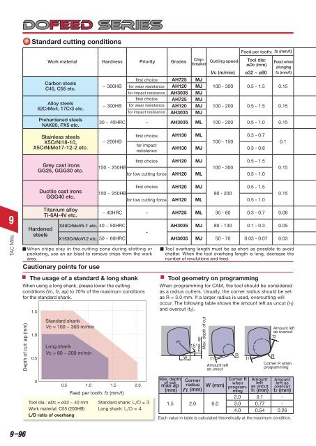
Standard cutting conditions<br />
Work material Hardness Priority Grades<br />
Carbon steels<br />
C45, C55 etc.<br />
Alloy steels<br />
42CrMo4, 17Cr3 etc.<br />
Prehardened steels<br />
NAK80, PX5 etc.<br />
~ 300HB<br />
~ 300HB<br />
first choice<br />
for wear resistance<br />
for impact resistance<br />
first choice<br />
for wear resistance<br />
for impact resistance<br />
AH725<br />
AH120<br />
AH3035<br />
AH725<br />
AH120<br />
AH3035<br />
Chipbreaker<br />
MJ<br />
MJ<br />
MJ<br />
MJ<br />
MJ<br />
MJ<br />
Cutting speed<br />
Vc (m/min)<br />
Feed per tooth: fz (mm/t)<br />
Tool dia:<br />
øDc (mm)<br />
ø32 ~ ø80<br />
Feed when<br />
plunging<br />
fz (mm/t)<br />
100 - 300 0.5 - 1.5 0.15<br />
100 - 200 0.5 - 1.5 0.15<br />
30 ~ 40HRC - AH3035 ML 100 - 200 0.5 - 1.0 0.15<br />
Stainless steels<br />
X5CrNi18-10,<br />
X5CrNiMo17-12-2 etc.<br />
~ 200HB<br />
first choice<br />
for impact<br />
resistance<br />
AH130 ML<br />
0.3 - 0.7<br />
100 - 150<br />
AH130 MJ 0.3 - 0.8<br />
0.1<br />
Grey cast irons<br />
GG25, GGG30 etc.<br />
first choice<br />
150 ~ 250HB<br />
for low cutting force<br />
AH120 MJ<br />
0.5 - 1.5<br />
100 - 300<br />
AH120 ML 0.5 - 1.0<br />
0.15<br />
Ductile cast irons<br />
GGG40 etc.<br />
first choice<br />
150 ~ 250HB<br />
for low cutting force<br />
AH120 MJ<br />
0.5 - 1.5<br />
80 - 200<br />
AH120 ML 0.5 - 1.0<br />
0.15<br />
9<br />
TAC Mills<br />
Hardened<br />
steels<br />
1.5<br />
Titanium alloy<br />
Ti-6AI-4V etc.<br />
~ 40HRC - AH725 ML 30 - 60 0.3 - 0.7 0.08<br />
X40CrMoV5-1 etc. 40 ~ 50HRC<br />
AH3035 MJ 80 - 130 0.1 - 0.3 0.05<br />
-<br />
X153CrMoV12 etc. 50 ~ 60HRC AH3035 MJ 50 - 70 0.03 - 0.07 0.03<br />
When chips stay in the cutting zone during slotting or<br />
pocketing, use an air blast to remove chips from the work<br />
area.<br />
Cautionary points for use<br />
The usage of a standard & long shank<br />
When using a long shank, please lower the cutting<br />
conditions (Vc, fz, ap) to 70% of the maximum conditions<br />
for the standard shank.<br />
Tool overhang length must be as short as possible to avoid<br />
chatter. When the tool overhang length is long, decrease the<br />
number of revolutions and feed.<br />
Tool geometry on programming<br />
When programming for CAM, the tool should be considered<br />
as a radius cutters. Usually, the corner radius should be set<br />
as R = 3.0 mm. If a larger radius is used, overcutting will<br />
occur. The following table shows the amount left as uncut (t 1 )<br />
and overcut (t 2 ).<br />
Depth of cut:ap (mm)<br />
1.0<br />
0.5<br />
Standard shank<br />
Vc = 100 ~ 300 m/min<br />
Long shank<br />
Vc = 80 ~ 200 m/min<br />
rε<br />
w<br />
15°<br />
max. ap<br />
Max. depth of cut<br />
t1 t1<br />
Amount left<br />
as uncut<br />
t2<br />
R R<br />
Amount left<br />
as overcut<br />
Corner R when<br />
programming<br />
0<br />
Tool dia.: øDc = ø32 ~ 40 mm<br />
Work material: C55 (200HB)<br />
L/D ratio of overhang<br />
0.5 1.0 1.5 2.0<br />
Feed per tooth: fz (mm/t)<br />
Standard shank<br />
Long shank<br />
<br />
<br />
max ap<br />
(mm)<br />
<br />
<br />
rε (mm)<br />
W (mm)<br />
1.5 2.0 6.0<br />
<br />
<br />
<br />
<br />
<br />
<br />
<br />
<br />
<br />
<br />
t1 (mm) t2 (mm)<br />
2.0 0.1 -<br />
3.0 0.77 -<br />
4.0 0.54 0.26<br />
Each value in table is calculated theoretically at the maximum condition.<br />
9–96


