PDFï¼7.7MB
PDFï¼7.7MB
PDFï¼7.7MB

Create successful ePaper yourself
Turn your PDF publications into a flip-book with our unique Google optimized e-Paper software.
EPH<br />
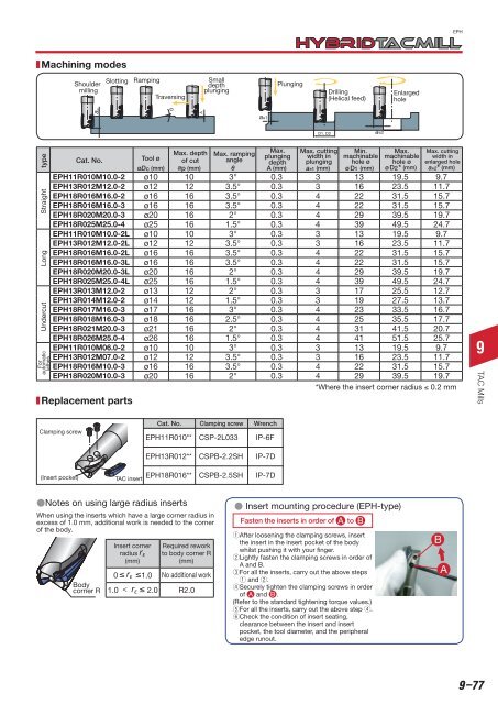
Machining modes<br />
Shoulder<br />
milling<br />
Slotting<br />
Ramping<br />
Traversing<br />
Small<br />
depth<br />
plunging<br />
Plunging<br />
Drilling<br />
(Helical feed)<br />
Enlarged<br />
hole<br />
ap<br />
A<br />
ae1<br />
D1, D2<br />
ae2<br />
For<br />
automatic Undercut Long Straight type<br />
lathes<br />
Cat. No.<br />
of cut<br />
depth plunging hole ø<br />
øDc (mm) ap (mm) θ A (mm) ae1 (mm) øD1 (mm)<br />
hole ø<br />
øD2* (mm) ae2* (mm)<br />
EPH11R010M10.0-2 ø10 10 3° 0.3 3 13 19.5 9.7<br />
EPH13R012M12.0-2 ø12 12 3.5° 0.3 3 16 23.5 11.7<br />
EPH18R016M16.0-2 ø16 16 3.5° 0.3 4 22 31.5 15.7<br />
EPH18R016M16.0-3 ø16 16 3.5° 0.3 4 22 31.5 15.7<br />
EPH18R020M20.0-3 ø20 16 2° 0.3 4 29 39.5 19.7<br />
EPH18R025M25.0-4 ø25 16 1.5° 0.3 4 39 49.5 24.7<br />
EPH11R010M10.0-2L ø10 10 3° 0.3 3 13 19.5 9.7<br />
EPH13R012M12.0-2L ø12 12 3.5° 0.3 3 16 23.5 11.7<br />
EPH18R016M16.0-2L ø16 16 3.5° 0.3 4 22 31.5 15.7<br />
EPH18R016M16.0-3L ø16 16 3.5° 0.3 4 22 31.5 15.7<br />
EPH18R020M20.0-3L ø20 16 2° 0.3 4 29 39.5 19.7<br />
EPH18R025M25.0-4L ø25 16 1.5° 0.3 4 39 49.5 24.7<br />
EPH13R013M12.0-2 ø13 12 2° 0.3 3 17 25.5 12.7<br />
EPH13R014M12.0-2 ø14 12 1.5° 0.3 3 19 27.5 13.7<br />
EPH18R017M16.0-3 ø17 16 3° 0.3 4 23 33.5 16.7<br />
EPH18R018M16.0-3 ø18 16 2.5° 0.3 4 25 35.5 17.7<br />
EPH18R021M20.0-3 ø21 16 2° 0.3 4 31 41.5 20.7<br />
EPH18R026M25.0-4 ø26 16 1.5° 0.3 4 41 51.5 25.7<br />
EPH11R010M06.0-2 ø10 10 3° 0.3 3 13 19.5 9.7<br />
EPH13R012M07.0-2 ø12 12 3.5° 0.3 3 16 23.5 11.7<br />
EPH18R016M10.0-3 ø16 16 3.5° 0.3 4 22 31.5 15.7<br />
EPH18R020M10.0-3 ø20 16 2° 0.3 4 29 39.5 19.7<br />
*Where the insert corner radius 0.2 mm<br />
Replacement parts<br />
Tool ø<br />
Max. depth<br />
Max. ramping<br />
angle<br />
Max.<br />
plunging<br />
Max. cutting<br />
width in<br />
Min.<br />
machinable<br />
Max.<br />
machinable<br />
Max. cutting<br />
width in<br />
enlarged hole<br />
9<br />
TAC Mills<br />
Clamping screw<br />
Cat. No. Clamping screw Wrench<br />
EPH11R010** CSP-2L033 IP-6F<br />
EPH13R012**<br />
CSPB-2.2SH<br />
IP-7D<br />
(Insert pocket)<br />
TAC insert EPH18R016**<br />
CSPB-2.5SH<br />
IP-7D<br />
Notes on using large radius inserts<br />
When using the inserts which have a large corner radius in<br />
excess of 1.0 mm, additional work is needed to the corner<br />
of the body.<br />
Body<br />
corner R<br />
Insert corner<br />
radius r ε<br />
(mm)<br />
<br />
<br />
<br />
0 r ε 1.0<br />
Required rework<br />
to body corner R<br />
(mm)<br />
No additional work<br />
1.0 < r ε 2.0 R2.0<br />
Insert mounting procedure (EPH-type)<br />
Fasten the inserts in order of A to B<br />
q After loosening the clamping screws, insert<br />
the insert in the insert pocket of the body<br />
whilst pushing it with your finger.<br />
w Lightly fasten the clamping screws in order of<br />
A and B.<br />
e For all the inserts, carry out the above steps<br />
q and w.<br />
r Securely tighten the clamping screws in order<br />
of A and B .<br />
(Refer to the standard tightening torque values.)<br />
t For all the inserts, carry out the above step r.<br />
y Check the condition of insert seating,<br />
clearance between the insert and insert<br />
pocket, the tool diameter, and the peripheral<br />
edge runout.<br />
B<br />
A<br />
9–77