
You also want an ePaper? Increase the reach of your titles
YUMPU automatically turns print PDFs into web optimized ePapers that Google loves.
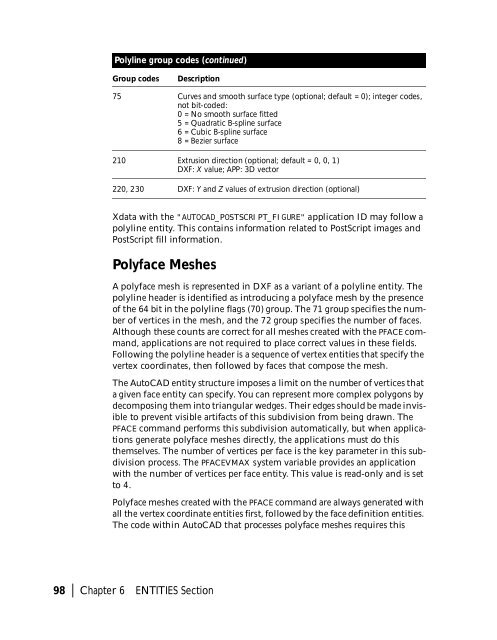
Polyline group codes (continued)<br />
Group codes<br />
Description<br />
75 Curves and smooth surface type (optional; default = 0); integer codes,<br />
not bit-coded:<br />
0 = No smooth surface fitted<br />
5 = Quadratic B-spline surface<br />
6 = Cubic B-spline surface<br />
8 = Bezier surface<br />
210 Extrusion direction (optional; default = 0, 0, 1)<br />
DXF: X value; APP: 3D vector<br />
220, 230 DXF: Y and Z values of extrusion direction (optional)<br />
Xdata with the "AUTOCAD_POSTSCRIPT_FIGURE" application ID may follow a<br />
polyline entity. This contains information related to PostScript images and<br />
PostScript fill information.<br />
Polyface Meshes<br />
A polyface mesh is represented in DXF as a variant of a polyline entity. The<br />
polyline header is identified as introducing a polyface mesh by the presence<br />
of the 64 bit in the polyline flags (70) group. The 71 group specifies the number<br />
of vertices in the mesh, and the 72 group specifies the number of faces.<br />
Although these counts are correct for all meshes created with the PFACE command,<br />
applications are not required to place correct values in these fields.<br />
Following the polyline header is a sequence of vertex entities that specify the<br />
vertex coordinates, then followed by faces that compose the mesh.<br />
The AutoCAD entity structure imposes a limit on the number of vertices that<br />
a given face entity can specify. You can represent more complex polygons by<br />
decomposing them into triangular wedges. Their edges should be made invisible<br />
to prevent visible artifacts of this subdivision from being drawn. The<br />
PFACE command performs this subdivision automatically, but when applications<br />
generate polyface meshes directly, the applications must do this<br />
themselves. The number of vertices per face is the key parameter in this subdivision<br />
process. The PFACEVMAX system variable provides an application<br />
with the number of vertices per face entity. This value is read-only and is set<br />
to 4.<br />
Polyface meshes created with the PFACE command are always generated with<br />
all the vertex coordinate entities first, followed by the face definition entities.<br />
The code within AutoCAD that processes polyface meshes requires this<br />
98 | Chapter 6 ENTITIES Section