
Create successful ePaper yourself
Turn your PDF publications into a flip-book with our unique Google optimized e-Paper software.
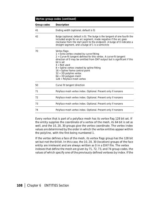
Vertex group codes (continued)<br />
Group codes<br />
Description<br />
41 Ending width (optional; default is 0)<br />
42 Bulge (optional; default is 0). The bulge is the tangent of one fourth the<br />
included angle for an arc segment, made negative if the arc goes<br />
clockwise from the start point to the endpoint. A bulge of 0 indicates a<br />
straight segment, and a bulge of 1 is a semicircle<br />
70 Vertex flags:<br />
1 = Extra vertex created by curve-fitting<br />
2 = Curve-fit tangent defined for this vertex. A curve-fit tangent<br />
direction of 0 may be omitted from DXF output but is significant if this<br />
bit is set<br />
4 = Not used<br />
8 = Spline vertex created by spline-fitting<br />
16 = Spline frame control point<br />
32 = 3D polyline vertex<br />
64 = 3D polygon mesh<br />
128 = Polyface mesh vertex<br />
50 Curve fit tangent direction<br />
71 Polyface mesh vertex index. Optional. Present only if nonzero<br />
72 Polyface mesh vertex index. Optional. Present only if nonzero<br />
73 Polyface mesh vertex index. Optional. Present only if nonzero<br />
74 Polyface mesh vertex index. Optional. Present only if nonzero<br />
Every vertex that is part of a polyface mesh has its vertex flag 128 bit set. If<br />
the entity supplies the coordinate of a vertex of the mesh, its 64 bit is set as<br />
well, and the 10, 20, 30 groups give the vertex coordinate. The vertex index<br />
values are determined by the order in which the vertex entities appear within<br />
the polyline, with the first being numbered 1.<br />
If the vertex defines a face of the mesh, its vertex flags group has the 128 bit<br />
set but not the 64 bit. In this case, the 10, 20, 30 (location) groups of the face<br />
entity are irrelevant and are always written as 0 in a DXF file. The vertex<br />
indexes that define the mesh are given by 71, 72, 73, and 74 group codes, the<br />
values of which specify one of the previously defined vertexes by index. If the<br />
108 | Chapter 6 ENTITIES Section