
You also want an ePaper? Increase the reach of your titles
YUMPU automatically turns print PDFs into web optimized ePapers that Google loves.
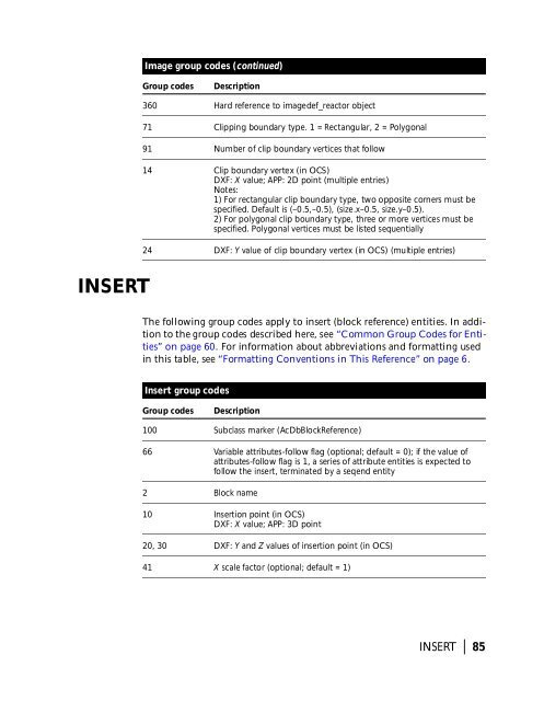
Image group codes (continued)<br />
Group codes<br />
Description<br />
360 Hard reference to imagedef_reactor object<br />
71 Clipping boundary type. 1 = Rectangular, 2 = Polygonal<br />
91 Number of clip boundary vertices that follow<br />
14 Clip boundary vertex (in OCS)<br />
DXF: X value; APP: 2D point (multiple entries)<br />
Notes:<br />
1) For rectangular clip boundary type, two opposite corners must be<br />
specified. Default is (–0.5,–0.5), (size.x–0.5, size.y–0.5).<br />
2) For polygonal clip boundary type, three or more vertices must be<br />
specified. Polygonal vertices must be listed sequentially<br />
24 DXF: Y value of clip boundary vertex (in OCS) (multiple entries)<br />
INSERT<br />
The following group codes apply to insert (block reference) entities. In addition<br />
to the group codes described here, see “Common Group Codes for Entities”<br />
on page 60. For information about abbreviations and formatting used<br />
in this table, see “Formatting Conventions in This Reference” on page 6.<br />
Insert group codes<br />
Group codes<br />
Description<br />
100 Subclass marker (AcDbBlockReference)<br />
66 Variable attributes-follow flag (optional; default = 0); if the value of<br />
attributes-follow flag is 1, a series of attribute entities is expected to<br />
follow the insert, terminated by a seqend entity<br />
2 Block name<br />
10 Insertion point (in OCS)<br />
DXF: X value; APP: 3D point<br />
20, 30 DXF: Y and Z values of insertion point (in OCS)<br />
41 X scale factor (optional; default = 1)<br />
INSERT | 85