
You also want an ePaper? Increase the reach of your titles
YUMPU automatically turns print PDFs into web optimized ePapers that Google loves.
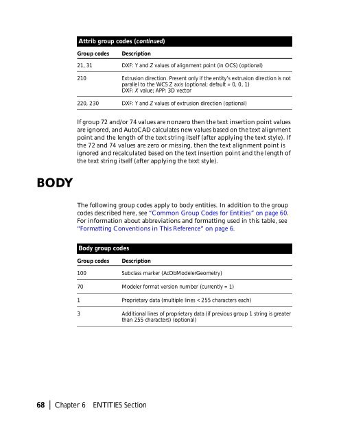
Attrib group codes (continued)<br />
Group codes<br />
Description<br />
21, 31 DXF: Y and Z values of alignment point (in OCS) (optional)<br />
210 Extrusion direction. Present only if the entity’s extrusion direction is not<br />
parallel to the WCS Z axis (optional; default = 0, 0, 1)<br />
DXF: X value; APP: 3D vector<br />
220, 230 DXF: Y and Z values of extrusion direction (optional)<br />
If group 72 and/or 74 values are nonzero then the text insertion point values<br />
are ignored, and AutoCAD calculates new values based on the text alignment<br />
point and the length of the text string itself (after applying the text style). If<br />
the 72 and 74 values are zero or missing, then the text alignment point is<br />
ignored and recalculated based on the text insertion point and the length of<br />
the text string itself (after applying the text style).<br />
BODY<br />
The following group codes apply to body entities. In addition to the group<br />
codes described here, see “Common Group Codes for Entities” on page 60.<br />
For information about abbreviations and formatting used in this table, see<br />
“Formatting Conventions in This Reference” on page 6.<br />
Body group codes<br />
Group codes<br />
Description<br />
100 Subclass marker (AcDbModelerGeometry)<br />
70 Modeler format version number (currently = 1)<br />
1 Proprietary data (multiple lines < 255 characters each)<br />
3 Additional lines of proprietary data (if previous group 1 string is greater<br />
than 255 characters) (optional)<br />
68 | Chapter 6 ENTITIES Section