
You also want an ePaper? Increase the reach of your titles
YUMPU automatically turns print PDFs into web optimized ePapers that Google loves.
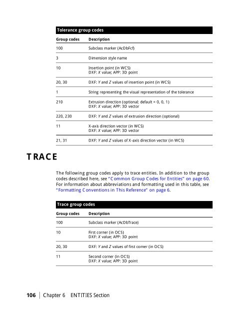
Tolerance group codes<br />
Group codes<br />
Description<br />
100 Subclass marker (AcDbFcf)<br />
3 Dimension style name<br />
10 Insertion point (in WCS)<br />
DXF: X value; APP: 3D point<br />
20, 30 DXF: Y and Z values of insertion point (in WCS)<br />
1 String representing the visual representation of the tolerance<br />
210 Extrusion direction (optional; default = 0, 0, 1)<br />
DXF: X value; APP: 3D vector<br />
220, 230 DXF: Y and Z values of extrusion direction (optional)<br />
11 X-axis direction vector (in WCS)<br />
DXF: X value; APP: 3D vector<br />
21, 31 DXF: Y and Z values of X-axis direction vector (in WCS)<br />
TRACE<br />
The following group codes apply to trace entities. In addition to the group<br />
codes described here, see “Common Group Codes for Entities” on page 60.<br />
For information about abbreviations and formatting used in this table, see<br />
“Formatting Conventions in This Reference” on page 6.<br />
Trace group codes<br />
Group codes<br />
Description<br />
100 Subclass marker (AcDbTrace)<br />
10 First corner (in OCS)<br />
DXF: X value; APP: 3D point<br />
20, 30 DXF: Y and Z values of first corner (in OCS)<br />
11 Second corner (in OCS)<br />
DXF: X value; APP: 3D point<br />
106 | Chapter 6 ENTITIES Section