BIOLOGY - microscopia.info
BIOLOGY - microscopia.info
BIOLOGY - microscopia.info
Create successful ePaper yourself
Turn your PDF publications into a flip-book with our unique Google optimized e-Paper software.
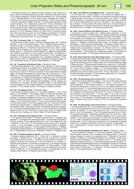
Color Projection Slides and Photomicrographs 35 mm 159<br />
1. The electricity atome, Fig 1. Struture of matter, elements 2. Fig 2. Structure of<br />
atom 3. Electric potentials. Elementary potential 4. Definition of the eletric current<br />
5. C.R.Tolman’s experiment 6. Electric tension and potential, Fig 1. Primary voltage<br />
7. Fig 2. Potential difference 8. The electric circuit. Amperage and voltage 9.<br />
Ohm’s law, Fig 1. Electric conductance and resistance 10. Fig 2. Linear resistors<br />
11. Electric resistance of metallic conductors 12. Temperature dependence of the<br />
specific resistance, Fig 1. Evidence by experiment 13. Fig 2. Derivation of the<br />
relation 14. The first law of Kirchhoff. Currents in the closed circuit 15. The first<br />
law of Kirchhoff. Primary voltage and voltage drop 16. What is primary voltage?<br />
17. The internal resistance 18. Loading of voltage sources, Fig 1. short circuit and<br />
idling ratio 19. Fig 2. Adaptation of power 20. Joule’s heat 21. The electric power,<br />
Fig 1. Work of the electric current 22. Fig 2. Wattage and wattmeter 23. Transformation<br />
of energy and efficiency, Fig 1. Input and output of energy 24. Fig 2.<br />
Transforming of current into heat 25. Fig 3. Rentability<br />
No. 1344. The Electric Field. 21 Projection Slides<br />
1. Phenomenons of atomic charge 2. Energy of resting charges, Fig 1. Frictional<br />
electricity 3. Fig 2. The electric charge 4. Fig 3. Effects between carriers 5.<br />
Transfer of charge 6. The electric influence, Fig 1. Collection of charge 7. Fig 2.<br />
Recharge by influence 8. Properties of electric field lines, Fig 1. Proof 9. Fig 2.<br />
Electric field lines between uni- and bipolar charges 10. Fig 3. Ditto. between<br />
bipolar charges 11. Fig 4. Ditto. of a plate capacitor 12. Matter in the electric field,<br />
Fig 1. Metal in electric field 13. Fig 2. Isolator in electric field 14. Distribution of<br />
charges on surfaces, Fig 1. Free mobility of electrons 15. Fig 2. Faraday’s cage<br />
experiment 16. Faraday’s cup experiment, Fig 1. Invariability of charges 17. Fig 2.<br />
Ditto. by touch contact 18. Peak effect, Fig 1. Distribution of charge on edges 19.<br />
Fig 2. Breaktrough charge 20. Van-de Graaff-Generator 21. Dust filters<br />
No. 1347. Quantities of the Electric Field. 25 Projection Slides<br />
1. The electric field strength E, Fig 1. Proof 2. Fig 2. Derivation 3. Surface density<br />
4. Displacement density 5. Correlations Fig 1. Dielectric and influence constants<br />
6. Fig 2. Field strenght on the surface of a charged sphere 7. Fig 3. Field strenght<br />
and radius of curvature 8. The law of Coulomb 9. Force effect between charged<br />
plates 10. Energy and potential of the electric field, Fig 1. Performance 11. Fig 2.<br />
Difference 12. Fig 3. Equipotential surface 13. Fig 4. Electric potential field 14.<br />
The condenser 15. Charge and discharge of a condenser, Fig 1. The discharged<br />
condenser 16. Fig 2. Charging of a condenser 17. Fig 3. Discharging of a condenser.<br />
Direction of flux 18. Fig 4. Charging and discharging 19. The capacity of a<br />
condenser, Fig 1. Derivation 20. Fig 2. Correlation of units 21. Fig 3. Experiment<br />
to change capacity 22. The coated condenser 23. Influence of insulators to the<br />
capacity 24. The multilayer insulator 25. Energy of a charged condenser<br />
No. 1350. The Magnetic Field. 25 Projection Slides<br />
1. The principle of magnetic poles, Fig 1. The earth’s magnetism 2. Fig 2. Force<br />
effects 3. Fig 3. Definition 4. The magnetic influence 5. Molecular magnetism, Fig<br />
1. Continual division of a magnet 6. Fig 2. Molecular magnets 7. Fig 3. Weis’s<br />
domains 8. Properties of magnetic force lines, Fig 1. Proof 9. Fig 2. Direction 10.<br />
Fig 3. Three dimensional field of a bar magnet 11. Pictures of field lines, Fig 1. Bar<br />
magnet 12. Fig 2. Horseshoe magnet 13. Fig 3. Force lines between bipolar poles<br />
14. Fig 4. Ditto. unipolar 15. Iron in the magnetic field, Fig 1. Force lines 16. Fig 2.<br />
Screening of magnetic fields 17. Magnetic field of a charged conductor 18. The<br />
cork-shrew principle 19. Direction of current 20. Field lines caused by conductors,<br />
Fig 1. Field lines of rectified parallel currents 21. Fig 2. Field lines of non-rectified<br />
parallel currents 22. Fig 3. Field lines of a current-carrying loop 23. Magnetic field<br />
of live coils, Fig 1. Cylinder coil 24. Fig 2. Poles 25. Fig 3. Toroidal coil<br />
No. 1353. Quantities of the magnetic Field. 19 Projection Slides<br />
1. The magnetic field strength H 2. Primary magnetic tension 3. Magnetic field<br />
strength H 4. Homogene and inhomogene fields 5. Field strength and distance<br />
from the conductor 6. The magnetic induction B 7. Unit 8. The magnetic flux, Fig<br />
1. Definition 9. Fig 2. Unit 10. Field strength and flux density, Fig 1. Induction<br />
constant 11. Fig 2. Permeability 12. Para- and diamagnetic stuffs 13. Magnetic<br />
induction B and field strength H 14. Field strength H and induction B 15. Relative<br />
permeability and field strength H 16. Magnetization and demagnetization of soft<br />
iron 17. Magnetization curve of steal 18. Magnetic resistance 19. Magnetic circle<br />
No. 1355. The Electromagnetic Induction. 23 Projection Slides<br />
1. Faraday’s induction experiment, Fig 1 2. Ditto. Fig 2 3. Induction in moving<br />
conductors 4. Direction of flux 5. The right hand rule 6. Moving of a conductor<br />
loop parallel with the field lines 7. Induction by approaching or removing of a<br />
magnet 8. Principle of the transformer 9. The clock hand rule 10. Induction 11.<br />
Principle of the generator 12. Derivation of induction law 13. Changing of induced<br />
voltage U1 14. The rule of Lenz 15. Experiment 16. Eddy currents 17. Selfinduction<br />
of a coil Fig 1 18. Self-induction of a coil by switching on and off the<br />
current 19. Ditto. fig. 2 20. The transformer principle 21. Coupling factor 22. The<br />
magnetic ignition system 23. Magnetic tape and tape recorder<br />
No. 1358. Force Effects in the Magnetic Field. 18 Projection Slides<br />
1. The left hand rule 2. Phasor diagram of force effects of magnetic field 3.<br />
Calculation of the force effect 4. Attraction and repulsion of movable conductors<br />
5. Equal direction of the current 6. Inverse direction of the current 7. Parallel<br />
streaming electrons 8. Derivation of force between parallel conductors 9. Definition<br />
10. Force effect between live coils, Fig 1. Attraction 11. Fig 2. Repulsion 12.<br />
Fig 3. Rotation 13. The principle of the direct-current motor 14. Life-coil torque in<br />
the magnetic field 15. Moving-coil instrument 16. Energy of the magnetic field 17.<br />
The tractive force of a magnet 18. The electromagnetic relay<br />
No. 1360. Chemical Effects of the Electric Current. 21 Projection Slides<br />
1. Conduction of current in liquids, Fig 1. Distilled water, electrolytes 2. Fig 2.<br />
Electrolytic dissociation 3. The Electrolysis, Fig 1. Copper sulphate as an electrolyte<br />
4. Fig 2. Diluted sulphuric acid as an electrolyte. Reduction and oxidation 5. The<br />
first electrolytic law of Faraday, Fig 1. Experiment 6. Fig 2. Derivation 7. The<br />
second electrolytic law of Faraday, Fig 1. Experiment 8. Fig 2. Derivation. Faraday’s<br />
constant 9. Transition of electrons between metals 10. Charge of metals in<br />
electrolytes 11. Base metals and noble metals 12. Deposit of noble metals 13.<br />
The electrochemical voltage row, Fig 1. Potential jump on double layers 14. Fig 2.<br />
Voltage values corresponding to hydrogen 15. Galvanic cells, Fig 1. Voltage<br />
characteristics 16. Fig 2. Construction and function 17. Fig 3. Leclanché cell 18.<br />
The accumulator 19. Discharging of a charged accumulator 20. Charging of a<br />
discharged accumulator 21. Cell voltage and acid density of accumulators<br />
No. 1363. Basic Properties of the Alternating Current. 17 Projection Slides<br />
1. Formation of the alternating voltage. Sinusoidal tension 2. Cycle periods. Angular<br />
velocity. Phase angle. Phasor diagram 3. Units of sinusoidal voltage 4. Advantages<br />
of the alternating current 5. Determination of the induced alternating voltage<br />
6. Arithmetic mean 7. Effective power. Derivation from Joule’s law 8. Construction<br />
of a three-phase A.C. generator 9. Phase displacement of amperages and voltages<br />
10. The star circuit. Linkage of voltages 11. The delta connection. Linkage of<br />
amperages 12. The three-phase current mains, Fig 1. Phasor diagram 13. Fig 2.<br />
Unbalanced load of three-phase current mains 14. Fig 3. Short-circuit 15. Fig 4.<br />
The star circuit delta connection 16. The magnetic rotating field, Fig 1. Generation<br />
17. Fig 2. The three-phase A.C. generator<br />
No. 1365. The Alternating Current Circuit, Part I. 24 Projection Slides<br />
1. Generation of phase displaced voltages 2. The sum of the phase displaced<br />
voltages 3. Characteristics 4. The Resistors R, L and C 5. The D.C. current<br />
(ohmic) resistance 6. The inductive resistance 7. The capacitive resistance 8.<br />
The effective resistance R 9. Coil in the A.C. circuit 10. Inductive resistance in the<br />
direct current circuit 11. Coil in the alternating current circuit 12. Condenser in the<br />
alternating current circuit 13. The capacitive resistance in the direct current circuit<br />
14. Condenser in the alternating current circuit 15. R and L in series circuit 16.<br />
The impedance. The phase angle 17. The loss angle 18. R, L and C in series<br />
circuit 19. The impedance. The phase angle 20. R and C in parallel (shunt) circuit.<br />
The currents 21. The impedance. The phase angle 22. The loss angle 23. R, L<br />
and C in parallel (shunt) circuit. Currents 24. Fig 2. The impedance. The phase<br />
angle<br />
No. 1368. The Alternating Current Circuit, Part II. 18 Projection Slides<br />
1. The series resonance, Fig 1. in series resonance circuit 2. Fig 2. The impedance<br />
3. Fig 3. The series resonance circuit 4. Fig 4. The resonance frequency. Thomson’s<br />
equation of oscillation 5. The parallel resonance, Fig 1. in parallel resonance<br />
circuit 6. Fig 2. The impedance 7. Fig 3. The parallel resonance circuit 8. Fig 4.<br />
The resonance frequency 9. Efficiency and power of the A.C. circuit, Fig 1. value<br />
of amperage and voltage 10. Fig 2. Efficiency diagram of D.C. current (ohmic)<br />
resistors 11. Fig 3. Ditto. of inductive resistors 12. Fig 4. Ditto. of capacitive resistors<br />
13. Fig 5. Ditto. of reactances and effective resistances 14. Fig 6. Reactive and<br />
apparent power 15. Fig 7. Active power, measuring 16. Compensation of reactive<br />
current, Fig 1. Loading of alternating current by reactances. Compensation 17.<br />
Fig 2. Compensation of reactive current, phase diagram 18. Fig 3. Ditto. in<br />
alternators<br />
No. 1370. Electromagnetic Oscillations and Waves. 19 Projection Slides<br />
1. The first equitation of Maxwell 2. The second equitation of Maxwell 3. The<br />
electromagnetic resonant circuit 4. Analogy to the spring pendulum 5. Reversal<br />
energy exchange 6. Losses in the resonant circuit 7. Deduction of Thomson’s<br />
equation of oscillation 8. Undamped oscillations of the pendulum 9. Ditto. in the<br />
resonant circuit by feedback 10. Open resonant circuit 11. The electric dipole.<br />
Magnetic and electric field lines 12. The electromagnetic field near the dipole 13.<br />
Field vectors of the electromagnetic waves 14. Propagation of electric and magnetic<br />
fields by dipole antenna 15. Wave velocity. Calculation 16. Ground waves and<br />
space waves. The blind area 17. Long waves 18. Short waves and ultra-short<br />
waves 19. The electromagnetic wave range


