- Page 1 and 2:
Aluminium Design and Construction C
- Page 3 and 4:
First published 1999 by E & FN Spon
- Page 5 and 6:
2.2.1 Rolling mill practice 2.2.2 P
- Page 7 and 8:
5 Limit state design and limiting s
- Page 9 and 10:
8.2.6 Use of interpolation for semi
- Page 11 and 12:
10.3.2 Inertias for a section with
- Page 13 and 14:
Preface Aluminium is easily the sec
- Page 15 and 16:
List of symbols The following symbo
- Page 17 and 18:
uu, vv principal axes w effective s
- Page 19 and 20:
1.1.3 The industrial metal It is on
- Page 21 and 22:
where A is the section area (mm 2 )
- Page 23 and 24:
1.3.1. The good points about alumin
- Page 25 and 26:
Deflection Because of the lower mod
- Page 27 and 28:
1.4.4 Establishment of the alloys I
- Page 29 and 30:
1.5.2 New technology Most of alumin
- Page 31 and 32:
large span, where self-weight is a
- Page 33 and 34:
These tend to be in all-aluminium c
- Page 35 and 36:
Close-up of the M-dec system, which
- Page 37 and 38:
Aluminium glazing system for commer
- Page 39 and 40:
Nat West Media Centre, Lords Cricke
- Page 41 and 42:
The main requirements for the produ
- Page 43 and 44:
in which t and w are in mm. These a
- Page 45 and 46:
Figure 2.1 Extrusion process (direc
- Page 47 and 48:
Figure 2.2 Typical extrusion die. t
- Page 49 and 50:
Figure 2.6 ‘Semi-hollow’ profil
- Page 51 and 52:
especially the stronger alloys in t
- Page 53 and 54:
Figure 2.9 Conventional profiles. 2
- Page 55 and 56:
2.4 TUBES By tubes we mean hollow s
- Page 57 and 58:
CHAPTER 3 Fabrication 3.1 PREPARATI
- Page 59 and 60:
Figure 3.1 Alternative designs for
- Page 61 and 62:
Figure 3.2 Thread insert. a coil-sp
- Page 63 and 64:
3.3 ARC WELDING 3.3.1 Use of arc we
- Page 65 and 66:
adjusted. The technique is claimed
- Page 67 and 68:
For welds of minimum or fatigue qua
- Page 69 and 70:
Figure 3.5 Friction-stir welding: s
- Page 71 and 72:
are, and the designer/fabricator mu
- Page 73 and 74:
cartridge, and mixing takes place a
- Page 75 and 76:
3.7.4 Painting Alloys having durabi
- Page 77 and 78:
Where a range is given, as for the
- Page 79 and 80:
will be only slightly above that fo
- Page 81 and 82:
heating the metal to a temperature
- Page 83 and 84:
Table 4.4 Characteristics of differ
- Page 85 and 86:
softening in the heat-affected zone
- Page 87 and 88:
60 alloys, are: BSEN.485 plate and
- Page 89 and 90:
Firure 4.3 Nominal composition and
- Page 91 and 92:
popular alloys in the series are: 6
- Page 93 and 94:
Figure 4.6 Variation of tensile str
- Page 95 and 96:
undercarriages of aircraft. They ar
- Page 97 and 98:
Figure 4.11 Minimum stress-strain c
- Page 99 and 100:
AC.51400 This is another non-heat-t
- Page 101 and 102:
times that of the actual pits) prod
- Page 103 and 104:
The severity of bimetallic corrosio
- Page 105 and 106:
Nominal loading. Nominal loads are
- Page 107 and 108:
2. Material factor (� m ). In the
- Page 109 and 110:
design does not, because stress at
- Page 111 and 112:
Table 5.2 Summary of limiting stres
- Page 113 and 114:
Figure 5.4 Plastic strain at workin
- Page 115 and 116:
example, a reduced value might be t
- Page 117 and 118:
The parameter � depends purely on
- Page 119 and 120:
CHAPTER 6 Heat-affected zone soften
- Page 121 and 122:
area of softening. With 7xxx-type m
- Page 123 and 124:
Figure 6.3 Typical hardness plots a
- Page 125 and 126:
6.4 SEVERITY OF HAZ SOFTENING 6.4.1
- Page 127 and 128:
Figure 6.6 Categories of welded joi
- Page 129 and 130:
Figure 6.10 One-inch rule, extent o
- Page 131 and 132:
e allowed for in design by replacin
- Page 133 and 134:
Figure 6.13 Predicted area (A z ) o
- Page 135 and 136:
Figure 6.15 Overlapping HAZs. nomin
- Page 137 and 138:
In determining A zp , an appropriat
- Page 139 and 140:
failure plane in the HAZ, close to
- Page 141 and 142:
With MIG welding, an electrode-posi
- Page 143 and 144:
CHAPTER 7 Plate elements in compres
- Page 145 and 146:
(a) Compression member elements The
- Page 147 and 148:
Table 7.1 Classification of element
- Page 149 and 150:
Figure 7.4 Slender internal element
- Page 151 and 152:
Figure 7.7 shows curves of � ° p
- Page 153 and 154:
(7.9a) (7.9b) The strain gradient c
- Page 155 and 156:
(through the centroid) for ß S . F
- Page 157 and 158:
Figure 7.13 Outstands under strain-
- Page 159 and 160:
Figure 7.15 Reinforced elements. Th
- Page 161 and 162:
Figure 7.18 Stiffener location for
- Page 163 and 164:
Figure 7.20 Slender reinforced inte
- Page 165 and 166:
CHAPTER 8 Beams 8.1 GENERAL APPROAC
- Page 167 and 168:
8.2.2 Section classification The di
- Page 169 and 170:
that for the gross section. It woul
- Page 171 and 172:
the usual manner. Line 1 in the fig
- Page 173 and 174:
1. Fully compact sections. The limi
- Page 175 and 176:
Figure 8.8 Transverse and longitudi
- Page 177 and 178:
8.3.4 Shear resistance of bars and
- Page 179 and 180:
Figure 8.12 Tension-field action. i
- Page 181 and 182:
Figure 8.14 Moment/shear interactio
- Page 183 and 184:
depending on the estimated degree o
- Page 185 and 186:
where a is the stiffener spacing an
- Page 187 and 188:
plates (if fitted), p v =limiting m
- Page 189 and 190:
ending moment diagram. Two cases ar
- Page 191 and 192:
Figure 8.23 Sections covered in Tab
- Page 193 and 194:
where: I yy , I vv =inertia about m
- Page 195 and 196:
post (Section 8.6.4) or by some oth
- Page 197 and 198:
Figure 8.26 Components of deflectio
- Page 199 and 200:
9.1.2 Classification of the cross-s
- Page 201 and 202:
hole. Alternatively, it might fail
- Page 203 and 204:
Figure 9.2 Limiting stress p b for
- Page 205 and 206:
The determination of l involves a c
- Page 207 and 208: Figure 9.6 Monosymmetric section. I
- Page 209 and 210: Figure 9.9 Limiting stress p b for
- Page 211 and 212: where s=� s /� t s =slenderness
- Page 213 and 214: Figure 9.11 Type-R sections covered
- Page 215 and 216: Figure 9.14 Four standardized profi
- Page 217 and 218: 9.7.2 Secondary bending in trusses
- Page 219 and 220: Table 9.5 Necessary checks for memb
- Page 221 and 222: Figure 9.18 Axial load with biaxial
- Page 223 and 224: 1. Tension members. The localized f
- Page 225 and 226: Figure 10.1 Symmetric plastic bendi
- Page 227 and 228: We now turn to monosymmetric sectio
- Page 229 and 230: distance of its centroid from the n
- Page 231 and 232: Figure 10.6 Elements of sections. I
- Page 233 and 234: 10.3.3 Product of inertia The produ
- Page 235 and 236: Usually the conditions are such as
- Page 237 and 238: Table 10.2 Torsion constant. Factor
- Page 239 and 240: Figure 10.12 Warping. Conventional
- Page 241 and 242: where b, t=element width and thickn
- Page 243 and 244: 10.5.3 Evaluation of warping When t
- Page 245 and 246: For sections where the position of
- Page 247 and 248: (10.31) where: e=distance that S li
- Page 249 and 250: 10.5.9 Asymmetric sections Before s
- Page 251 and 252: CHAPTER 11 Joints This chapter cons
- Page 253 and 254: the use of limiting stresses taken
- Page 255 and 256: and the summation is made for all t
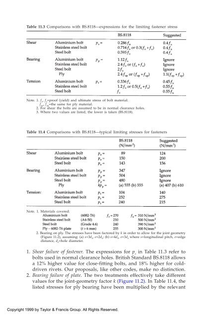
- Page 257: Figure 11.3 Interaction diagram for
- Page 261 and 262: 3. The design is satisfactory if fo
- Page 263 and 264: When the method of surface preparat
- Page 265 and 266: 11.3.3 Weld force arising In many c
- Page 267 and 268: Table 11.6 Limiting stress p w (N/m
- Page 269 and 270: where p a =limiting stress for unwe
- Page 271 and 272: Figure 11.11 Interaction diagram fo
- Page 273 and 274: Manufacturers of structural adhesiv
- Page 275 and 276: 11.4.6 Creep Shear strength figures
- Page 277 and 278: Figure 11.15 Effect of glue-line th
- Page 279 and 280: Table 11.7 and Figure 11.17 provide
- Page 281 and 282: 11.4.11 Resistance calculations for
- Page 283 and 284: high value reflects the various unc
- Page 285 and 286: therefore usually presented in term
- Page 287 and 288: For example: The loading spectrum i
- Page 289 and 290: act on the structure. However, BS.8
- Page 291 and 292: Figure 12.4 Crack propagation: (a)
- Page 293 and 294: 12.5 CLASSIFICATION OF DETAILS 12.5
- Page 295 and 296: i.e. a joint extending in the same
- Page 297 and 298: when the design life is low or when
- Page 299 and 300: Methods (2) and (3) are difficult t
- Page 301: it reverts to line 1. The slope s o


