

Contents Telektronikk - Telenor
Contents Telektronikk - Telenor
Contents Telektronikk - Telenor

Create successful ePaper yourself
Turn your PDF publications into a flip-book with our unique Google optimized e-Paper software.
frames where the router is destination are<br />
identified as outgoing traffic.<br />
These definitions assume that the internal<br />
traffic on the LAN does not go via the<br />
router; which is usually true, unless the<br />
router also acts as an internal server or<br />
several LAN segments are connected<br />
directly to the router. In the latter case,<br />
filter functions in the protocol analyser<br />
can be utilized to extract the WAN traffic,<br />
see [2].<br />
2.3 Technical constraints<br />
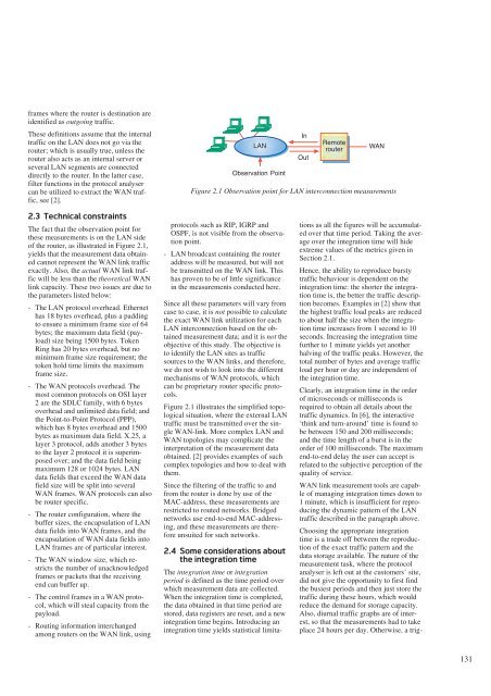
The fact that the observation point for<br />
these measurements is on the LAN side<br />
of the router, as illustrated in Figure 2.1,<br />
yields that the measurement data obtained<br />
cannot represent the WAN link traffic<br />
exactly. Also, the actual WAN link traffic<br />
will be less than the theoretical WAN<br />
link capacity. These two issues are due to<br />
the parameters listed below:<br />
- The LAN protocol overhead. Ethernet<br />
has 18 bytes overhead, plus a padding<br />
to ensure a minimum frame size of 64<br />
bytes; the maximum data field (payload)<br />
size being 1500 bytes. Token<br />
Ring has 20 bytes overhead, but no<br />
minimum frame size requirement; the<br />
token hold time limits the maximum<br />
frame size.<br />
- The WAN protocols overhead. The<br />
most common protocols on OSI layer<br />
2 are the SDLC family, with 6 bytes<br />
overhead and unlimited data field; and<br />
the Point-to-Point Protocol (PPP),<br />
which has 8 bytes overhead and 1500<br />
bytes as maximum data field. X.25, a<br />
layer 3 protocol, adds another 3 bytes<br />
to the layer 2 protocol it is superimposed<br />
over; and the data field being<br />
maximum 128 or 1024 bytes. LAN<br />
data fields that exceed the WAN data<br />
field size will be split into several<br />
WAN frames. WAN protocols can also<br />
be router specific.<br />
- The router configuration, where the<br />
buffer sizes, the encapsulation of LAN<br />
data fields into WAN frames, and the<br />
encapsulation of WAN data fields into<br />
LAN frames are of particular interest.<br />
- The WAN window size, which restricts<br />
the number of unacknowledged<br />
frames or packets that the receiving<br />
end can buffer up.<br />
- The control frames in a WAN protocol,<br />
which will steal capacity from the<br />
payload.<br />
- Routing information interchanged<br />
among routers on the WAN link, using<br />
LAN<br />
Observation Point<br />
protocols such as RIP, IGRP and<br />
OSPF, is not visible from the observation<br />
point.<br />
- LAN broadcast containing the router<br />
address will be measured, but will not<br />
be transmitted on the WAN link. This<br />
has proven to be of little significance<br />
in the measurements conducted here.<br />
Since all these parameters will vary from<br />
case to case, it is not possible to calculate<br />
the exact WAN link utilization for each<br />
LAN interconnection based on the obtained<br />
measurement data; and it is not the<br />
objective of this study. The objective is<br />
to identify the LAN sites as traffic<br />
sources to the WAN links, and therefore,<br />
we do not wish to look into the different<br />
mechanisms of WAN protocols, which<br />
can be proprietary router specific protocols.<br />
Figure 2.1 illustrates the simplified topological<br />
situation, where the external LAN<br />
traffic must be transmitted over the single<br />
WAN-link. More complex LAN and<br />
WAN topologies may complicate the<br />
interpretation of the measurement data<br />
obtained. [2] provides examples of such<br />
complex topologies and how to deal with<br />
them.<br />
Since the filtering of the traffic to and<br />
from the router is done by use of the<br />
MAC-address, these measurements are<br />
restricted to routed networks. Bridged<br />
networks use end-to-end MAC-addressing,<br />
and these measurements are therefore<br />
unsuited for such networks.<br />
2.4 Some considerations about<br />
the integration time<br />
The integration time or integration<br />
period is defined as the time period over<br />
which measurement data are collected.<br />
When the integration time is completed,<br />
the data obtained in that time period are<br />
stored, data registers are reset, and a new<br />
integration time begins. Introducing an<br />
integration time yields statistical limita-<br />
In<br />
Out<br />
Remote<br />
router<br />
WAN<br />
Figure 2.1 Observation point for LAN interconnection measurements<br />
tions as all the figures will be accumulated<br />
over that time period. Taking the average<br />
over the integration time will hide<br />
extreme values of the metrics given in<br />
Section 2.1.<br />
Hence, the ability to reproduce bursty<br />
traffic behaviour is dependent on the<br />
integration time: the shorter the integration<br />
time is, the better the traffic description<br />
becomes. Examples in [2] show that<br />
the highest traffic load peaks are reduced<br />
to about half the size when the integration<br />
time increases from 1 second to 10<br />
seconds. Increasing the integration time<br />
further to 1 minute yields yet another<br />
halving of the traffic peaks. However, the<br />
total number of bytes and average traffic<br />
load per hour or day are independent of<br />
the integration time.<br />
Clearly, an integration time in the order<br />
of microseconds or milliseconds is<br />
required to obtain all details about the<br />
traffic dynamics. In [6], the interactive<br />
‘think and turn-around’ time is found to<br />
be between 150 and 200 milliseconds;<br />
and the time length of a burst is in the<br />
order of 100 milliseconds. The maximum<br />
end-to-end delay the user can accept is<br />
related to the subjective perception of the<br />
quality of service.<br />
WAN link measurement tools are capable<br />
of managing integration times down to<br />
1 minute, which is insufficient for reproducing<br />
the dynamic pattern of the LAN<br />
traffic described in the paragraph above.<br />
Choosing the appropriate integration<br />
time is a trade off between the reproduction<br />
of the exact traffic pattern and the<br />
data storage available. The nature of the<br />
measurement task, where the protocol<br />
analyser is left out at the customers’ site,<br />
did not give the opportunity to first find<br />
the busiest periods and then just store the<br />
traffic during these hours, which would<br />
reduce the demand for storage capacity.<br />
Also, diurnal traffic graphs are of interest,<br />
so that the measurements had to take<br />
place 24 hours per day. Otherwise, a trig-<br />
131


