Operating instructions - EWM Hightec Welding GmbH
Operating instructions - EWM Hightec Welding GmbH
Operating instructions - EWM Hightec Welding GmbH

Create successful ePaper yourself
Turn your PDF publications into a flip-book with our unique Google optimized e-Paper software.
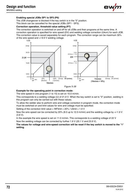
Design and functionMIG/MAG weldingEnabling special JOBs SP1 to SP3 (P6)The JOB changeover is blocked if the key switch is in the “0” position.This block can be cancelled for the special JOBs (SP1 - SP3).Correction operation, threshold value setting (P7)The correction operation is switched on and off for all JOBs and their programs at the same time. Acorrection operation is specified for wire speed (DV) and welding voltage correction (Ukorr) for each JOB.The correction value is saved separately for each program. The correction range can be maximum 30%of the wire speed and +/-9.9 V welding voltage.Figure 5-38Example for the operating point in correction mode:The wire speed in one program (1 to 15) is set on 10.0 m/min.This corresponds to a welding voltage (U) of 21,9 V. When the key switch is set to "0" position, welding inthis program can only be carried out with these values.To allow the welder also to perform wire and voltage correction in program mode, the correction modemust be switched on and limit values for wire and voltage must be specified.Setting of the correction limit value = WFlimit = 20% / Ulimit = 1.9 VNow the wire speed can be corrected by 20% (8.0 up to 12.0 m/min) and the welding voltage by +/-1.9 V(3.8 V).In the example the wire speed is set on 11.0 m/min. This corresponds to a welding voltage of 22 VNow the welding voltage can be corrected by further 1.9 V (20.1 V and 23.9 V).The values for voltage and wire-speed correction will be reset if the key switch is moved to the "1"setting.72099-005234-EW50116.04.2012