BRIDGE REPAIR/REHABILITATION FEASIBILITY STUDY
Bridge Repair_Rehabilitation Feasibility Study - Town to Chatham
Bridge Repair_Rehabilitation Feasibility Study - Town to Chatham
You also want an ePaper? Increase the reach of your titles
YUMPU automatically turns print PDFs into web optimized ePapers that Google loves.
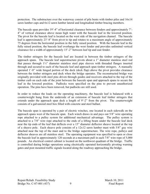
protection. The substructure over the waterway consist of pile bents with timber piles and 16x14<br />
sawn lumber caps and 6x12 sawn lumber lateral and longitudinal timber bracing members.<br />
The bascule span provides 19’-4” of horizontal clearance between fenders and approximately 7’-<br />
4” of vertical clearance above mean high water with the bascule leaf in the lowered position.<br />
The pivot for the bascule leaf is located on the west side of the navigation channel. The bascule<br />
leaf is approximately 23’-8” from pivot to tip and rotates to a maximum angle of approximately<br />
75 degrees from the horizontal position in the fully raised position. With the bascule leaf in the<br />
fully raised position, the bascule leaf overhangs the west fender and provides unlimited vertical<br />
clearance for a width of approximately 15’-2” between leaf tip and east fender.<br />
The timber stringers for the bascule leaf are located in between the timber stringers of the<br />
approach spans. The bascule leaf superstructure pivots about a 1” diameter stainless steel rod<br />
that passes through 1¼” diameter stainless steel pipe sleeves with threaded flanges inserted<br />
through and secured to each of the bascule leaf and approach span timber stringers. A manually<br />
operated 1’-8” wide hinged portion of the deck (deck flap) above the pivot provides clearance<br />
between the timber stringers and deck when the bridge operates. The reconstructed bridge was<br />
originally provided with steel pins driven through guides and receivers attached to the top of the<br />
timber curb on each side of the joint between the bascule span and approach spans to secure the<br />
leaf in the lowered position. Padlocks were specified on the pins to prevent unauthorized<br />
operation. The pins have been removed, but padlocks are still used.<br />
In order to reduce the loads on the operating machinery, the bascule leaf is balanced with a<br />
counterweight hung from the underside of an extension of bascule leaf timber stringers that<br />
extends under the approach span deck a length of 9’-2” from the pivot. The counterweight<br />
consists of a galvanized steel box filled with concrete and steel ballast.<br />
The bascule span is operated by a pair of electric winches, one located in each sidewalk on the<br />
approach spans west of the bascule span. Each winch draws in and pays out 5/8” wire operating<br />
rope attached to a pulley system for additional mechanical advantage. The pulley system is<br />
attached to a 7/8” wire rope attached to the ends of a lifting beam under the bascule leaf deck<br />
near the tip ends of the leaf that deflects over a 15” diameter deflector sheave located at the top<br />
of a sheave pole. Each sheave pole consists of a 12x12 sawn lumber mast with 5/8” guy wire<br />
attached near the top of the mast and to the bridge superstructure. The wire rope, pulleys and<br />
deflector sheaves are all stainless steel. The operating equipment was specified to open or close<br />
the bascule leaf in approximately 120 seconds at a maximum pull in each 7/8” wire rope of 5,000<br />
pounds. An electrical control cabinet is located on the northwest quadrant of the bridge. Traffic<br />
is controlled during bridge operations using electrically operated horizontally pivoting warning<br />
gates and post mounted traffic signals located along the roadway approaching the bridge.<br />
Repair/Rehab. Feasibility Study March 10, 2011<br />
Bridge No. C-07-001 (437) 9 Final Report


