BRIDGE REPAIR/REHABILITATION FEASIBILITY STUDY
Bridge Repair_Rehabilitation Feasibility Study - Town to Chatham
Bridge Repair_Rehabilitation Feasibility Study - Town to Chatham

Create successful ePaper yourself
Turn your PDF publications into a flip-book with our unique Google optimized e-Paper software.
(Lopez-Anido et al. 2004c). For example, four steel-threaded rods<br />
with a diameter of 19 mm were used at each end of the FRP<br />
composite shields as shear connectors to repair wood piles<br />
(Lopez-Anido et al. 2003). The steel-threaded rods were spaced<br />
along the pile axis at approximately 102 mm intervals and rotated<br />
approximately 30° in the circumferential direction. When a polyurethane<br />
chemical grout is used in wood pile strengthening, then<br />
shear connectors are required to develop the structural capacity of<br />
the FRP composite shield. For the cement-based grout, metal<br />
shear connectors are not required.<br />
Underwater-Curing Adhesive<br />
An underwater-curing adhesive is required to bond the FRP composite<br />
shells together and provide composite action. The selection<br />
criteria for the adhesive were (1) ability to cure underwater, (2)<br />
ability to be applied underwater, (3) ability to bond well to vinyl<br />
ester composites, and (4) durability in waterfront environments<br />
(Lopez-Anido et al. 2004b). The adhesive selected is an<br />
underwater-curing two-part epoxy adhesive. Part A is the epoxy<br />
resin and Part B is the hardener (Superior 2000). Part A, which is<br />
modified bisphenol-A polyglycidyl ether, is a viscous light amber<br />
liquid with mild odor that comes in various consistencies. Part B,<br />
which is a modified polyamine, is a viscous liquid with a fishy<br />
odor and comes in various colors and consistencies. Blue color<br />
was selected for the pile repair application because it is visible<br />
through the FRP composite shells and therefore would make it<br />
possible to visually inspect the adhesive spread area between<br />
shells. A paste consistency applied with a trowel is recommended<br />
for underwater applications. In the laboratory prototypes, the adhesive<br />
was applied around the circumference and along the length<br />
of the FRP composite cylindrical shells covering all the contact<br />
area between two shells.<br />
Polymer Concrete Coating<br />
A polymer concrete coating or overlay is required to develop<br />
friction between the FRP composite shell and the cement-based<br />
structural grout. The polymer concrete selected is a twocomponent,<br />
low-modulus polysulphide epoxy-based wearing<br />
course (TRANSPO 2000). Components A (resin) and B (hardener)<br />
are mixed in a 2:1 volume ratio. The selected polymer concrete<br />
is an impervious overlay typically used for restoring bridge<br />
decks and other pavements and applied with a thickness of 6 to 12<br />
mm (TRANSPO 2000). In the wood pile repair application a<br />
polymer concrete layer with a thickness of 3 mm was applied on<br />
the interior surface of the innermost shell. First, the epoxy was<br />
applied using rollers, and then standard basalt sand was broadcast<br />
as the aggregate. The epoxy bonded well to the vinyl ester composite<br />
shell. The aggregate created a rough surface, which provided<br />
adequate interlocking with the cement-based grout. It was<br />
found that the shear strength at the interface between the cementbased<br />
grout and the innermost FRP composite shell was significantly<br />
increased due to the polymer concrete coating (Lopez-<br />
Anido et al. 2004a).<br />
Fabrication of Fiber-Reinforced Polymer Composite<br />
Shells<br />
The first manufacturing process used to fabricate the FRP composite<br />
cylindrical shells with the longitudinal slit was wet layup<br />
with vacuum bagging compaction. In this fabrication process the<br />
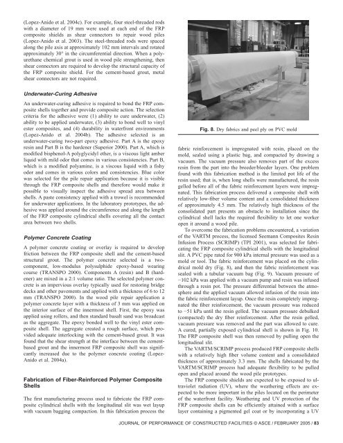
Fig. 8. Dry fabrics and peel ply on PVC mold<br />
fabric reinforcement is impregnated with resin, placed on the<br />
mold, sealed using a plastic bag, and compacted by drawing a<br />
vacuum. The vacuum pressure also removes part of the excess<br />
resin from the part into the breeder/bleeder layers. One problem<br />
found with this fabrication method is the limited pot life of the<br />
resin used; that is, when long shells were manufactured, the resin<br />
gelled before all of the fabric reinforcement layers were impregnated.<br />
This fabrication process delivered a composite shell with<br />
relatively low-fiber volume content and a consolidated thickness<br />
of approximately 4.5 mm. The relatively high thickness of the<br />
consolidated part presents an obstacle to installation since the<br />
cylindrical shell lacks the required flexibility to let one worker<br />
open it around a wood pile.<br />
To overcome the fabrication problems encountered, a variation<br />
of the VARTM process, the licensed Seemann Composites Resin<br />
Infusion Process (SCRIMP) (TPI 2001), was selected for fabricating<br />
the FRP composite cylindrical shells with the longitudinal<br />
slit. A PVC pipe rated for 900 kPa internal pressure was used as a<br />
mold or tool. The fabric reinforcement was placed on the cylindrical<br />
mold dry (Fig. 8), and then the fabric reinforcement was<br />
sealed with a tubular vacuum bag (Fig. 9). Vacuum pressure of<br />
−102 kPa was applied with a vacuum pump and resin was infused<br />
through a resin pot. The pressure differential between the atmosphere<br />
and the applied vacuum allowed infusion of the resin into<br />
the fabric reinforcement layup. Once the resin completely impregnated<br />
the fiber reinforcement, the vacuum pressure was reduced<br />
to −51 kPa until the resin gelled. The vacuum pressure debulked<br />
(compacted) the dry fiber reinforcement. After the resin gelled,<br />
vacuum pressure was removed and the part was allowed to cure.<br />
A cured, partially exposed cylindrical shell is shown in Fig. 10.<br />
The FRP composite shell was then removed by pulling open the<br />
longitudinal slit.<br />
The VARTM/SCRIMP process produced FRP composite shells<br />
with a relatively high fiber volume content and a consolidated<br />
thickness of approximately 3.3 mm. The shells fabricated by the<br />
VARTM/SCRIMP process had adequate flexibility to be pulled<br />
open and placed around the wood pile prototypes.<br />
The FRP composite shields are expected to be exposed to ultraviolet<br />
radiation (UV), where the weathering effects are expected<br />
to be more important in the piles located on the perimeter<br />
of the waterfront facility. Weathering and UV protection of the<br />
FRP composite shells can be efficiently attained with a surface<br />
layer containing a pigmented gel coat or by incorporating a UV<br />
JOURNAL OF PERFORMANCE OF CONSTRUCTED FACILITIES © ASCE / FEBRUARY 2005 / 83