BRIDGE REPAIR/REHABILITATION FEASIBILITY STUDY
Bridge Repair_Rehabilitation Feasibility Study - Town to Chatham
Bridge Repair_Rehabilitation Feasibility Study - Town to Chatham

You also want an ePaper? Increase the reach of your titles
YUMPU automatically turns print PDFs into web optimized ePapers that Google loves.
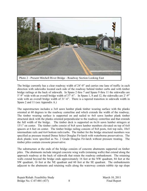
Photo 2 - Present Mitchell River Bridge - Roadway Section Looking East<br />
The bridge currently has a clear roadway width of 24’-0” and carries one lane of traffic in each<br />
direction with sidewalks located each side of the roadway behind timber curbs and with timber<br />
bridge railings at the back of sidewalk. In Spans 2 thru 7 and Spans 9 thru 11 the sidewalks are<br />
5’-9” wide with an overall bridge width of 37’-6”. In Spans 1, 8 and 12, the sidewalks are 2’-9”<br />
wide with an overall bridge width of 31’-6”. There is a tapered transition in sidewalk width in<br />
Spans 2 and 11 (see Appendix A.)<br />
The superstructure includes a 3x8 sawn lumber plank timber wearing surface with the planks<br />
oriented at 60 degrees to the roadway centerline and which extends the width of the roadway.<br />
The timber wearing surface is supported on and nailed to 4x8 sawn lumber plank timber<br />
structural deck with the planks oriented perpendicular to the roadway centerline and that extends<br />
the full width of the bridge. The timber deck is supported on 6x16 sawn lumber stringers at<br />
15½” on center. The timber curbs consist of 8x8 sawn lumber members elevated on top of 6x8<br />
spacers at 6 feet on center. The timber bridge railing consists of 8x8 posts, 6x6 top rails, 10x5<br />
intermediate rails and 6x4 bottom rails/curbs. The timber for the bridge structural members was<br />
specified as pressure treated Dense Select Douglas Fir-larch with waterborne preservatives. The<br />
deck planks were specified as No. 2 Grade Douglas Fir-larch without pressure treating. The<br />
timber piles contain creosote preservative.<br />
The substructure at the ends of the bridge consists of concrete abutments supported on timber<br />
piles. The abutments include integral concrete wing walls (retaining walls) that extend along the<br />
approach roadway at the back of sidewalk that retain the roadway embankment. The retaining<br />
walls extend beyond the bridge ends approximately 16 feet at the NW quadrant, 84 feet at the<br />
SW quadrant, 16 feet at the NE quadrant and 60 feet at the SE quadrant. The embankments<br />
adjacent to the abutments and retaining walls along the waterway contain rubble rip rap slope<br />
Repair/Rehab. Feasibility Study March 10, 2011<br />
Bridge No. C-07-001 (437) 8 Final Report