BRIDGE REPAIR/REHABILITATION FEASIBILITY STUDY
Bridge Repair_Rehabilitation Feasibility Study - Town to Chatham
Bridge Repair_Rehabilitation Feasibility Study - Town to Chatham

Create successful ePaper yourself
Turn your PDF publications into a flip-book with our unique Google optimized e-Paper software.
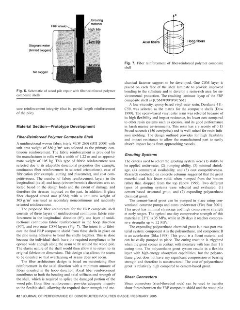
Fig. 7. Fiber reinforcement of fiber-reinforced polymer composite<br />
shell<br />
Fig. 6. Schematic of wood pile repair with fiber-reinforced polymer<br />
composite shells<br />
sure reinforcement integrity (that is, partial length reinforcement<br />
of the pile).<br />
Material Section—Prototype Development<br />
Fiber-Reinforced Polymer Composite Shell<br />
A unidirectional woven fabric (style VEW 260) (BTI 2000) with<br />
unit area weight of 880 g/m 2 was selected as the primary continuous<br />
reinforcement. The fabric reinforcement is provided by<br />
the manufacturer in rolls with a width of 1.22 m and an approximate<br />
weight of 105 kg. This type of fabric reinforcement was<br />
selected due to its adaptable directional properties (for example,<br />
continuous fiber reinforcement in selected orientations), ease of<br />
fabrication (for example, cutting and placement), and cost competitiveness.<br />
The number of fabric reinforcement layers in the<br />
longitudinal (axial) and hoop (circumferential) directions was selected<br />
based on the design loads and the extent of damage, and<br />
therefore the stresses imposed on the part. In addition, E-glass<br />
fiber chopped strand mat (CSM) with a unit area weight of<br />
305 g/m 2 was used as secondary noncontinuous and randomly<br />
oriented reinforcement.<br />
The proposed fiber architecture for the FRP composite shell<br />
consists of three layers of unidirectional continuous fabric reinforcement<br />
in the longitudinal direction (0°), one layer of unidirectional<br />
continuous fabric reinforcement in the hoop direction<br />
(90°), and two outer CSM layers (Fig. 7). The intent is to fabricate<br />
the final FRP composite shield from these shells in place on<br />
the pile using adhesive to bond the shells together. This is done<br />
because the individual shells have the required compliance to be<br />
opened wide enough along the seam to fit around the wood pile.<br />
The elastic nature of the shell would then allow it to return to its<br />
original fabrication dimensions. This design also allows the seams<br />
to be oriented so that overlapping of seams does not occur.<br />
The fiber architecture design is based on maximizing fiber<br />
reinforcement in the axial direction with a minimum amount of<br />
fibers oriented in the hoop direction. Axial fiber reinforcement<br />
contributes to both the bending and axial stiffness and strength of<br />
the shell, which is required to splice the damaged portion of the<br />
wood pile. Hoop fiber reinforcement provides adequate integrity<br />
to the flexible shell, allowing the required shear strength and mechanical<br />
fastener support to be developed. One CSM layer is<br />
placed on each face of the shell laminate to provide improved<br />
bonding to the substrate and to develop a resin-rich area for environmental<br />
protection. The resulting laminate layup of the FRP<br />
composite shell is [CSM/0/90/0/0/CSM].<br />
A low-viscosity, epoxy-based vinyl ester resin, Derakane 411-<br />
C50, was selected as the matrix for the composite shells (Dow<br />
1999). The epoxy-based vinyl ester resin was selected because of<br />
its high flexibility and impact resistance, its lower cost compared<br />
to other resin systems such as epoxies, and its good performance<br />
in harsh marine environments. This resin has a viscosity of 0.15<br />
Pascal seconds (150 centipoise) and is well suited for resin infusion<br />
molding. The design outlined provides for high flexibility<br />
and impact resistance to allow the manufactured part to easily<br />
absorb impact loads from approaching vessels.<br />
Grouting Systems<br />
The criteria used to select the grouting system were (1) ability to<br />
be applied underwater, (2) pumping ability, (3) minimal shrinkage,<br />
(4) commercial availability, and (5) cost competitiveness.<br />
Research conducted on concrete columns suggested that the grout<br />
material used has fewer voids when pumped from the bottom<br />
rather than dropped from the top (Snow 1995). Two different<br />
types of grouting systems were selected and evaluated: (1)<br />
cement-based structural grout, and (2) expanding polyurethane<br />
chemical grout.<br />
The cement-based grout can be pumped in place using conventional<br />
concrete pumps and cures underwater (Five Star 2001).<br />
This grout has minimal shrinkage and high compressive strength<br />
at early stages. The typical one-day compressive strength of this<br />
material at 23°C is 35 MPa, while at 28 days it reaches compressive<br />
strengths up to 52 MPa.<br />
The expanding polyurethane chemical grout is a two-part material<br />
system: component A is the polyurethane, and component B<br />
is an accelerator (Sika 1998). This grout is a fluent material and<br />
can be easily pumped to place. The curing reaction is triggered<br />
when the grout comes in contact with moisture with less than 1 h<br />
curing time. The polyurethane grout system results in a flexible<br />
layer with high-energy absorption capabilities, but the polyurethane<br />
grout does not have any significant compression or bearing<br />
strength and therefore is nonstructural. The cost of polyurethane<br />
grout is relatively high compared to cement-based grout.<br />
Shear Connectors<br />
Shear connectors (steel-threaded rods) can be used to transfer<br />
shear forces between the FRP composite shield and the wood pile<br />
82 / JOURNAL OF PERFORMANCE OF CONSTRUCTED FACILITIES © ASCE / FEBRUARY 2005