- Page 2 and 3:
Building Services Engineering
- Page 4 and 5:
Building Services Engineering Fifth
- Page 6 and 7:
Contents Preface to fifth edition A
- Page 8 and 9:
Contents vii Sick building syndrome
- Page 10 and 11:
Contents ix Circuit design 294 Cabl
- Page 12 and 13:
Preface to fifth edition Building S
- Page 14 and 15:
Acknowledgements I am particularly
- Page 16 and 17:
Units and constants xv Table 2 Mult
- Page 18 and 19:
Symbols xvii Symbol Description Uni
- Page 20:
Symbols xix Symbol Description Unit
- Page 23 and 24:
2 Built environment Introduction Th
- Page 25 and 26:
4 Built environment Ventilation The
- Page 27 and 28:
6 Built environment (a) At full occ
- Page 29 and 30:
8 Built environment Table 1.2 Compa
- Page 31 and 32:
10 Built environment Because of the
- Page 33 and 34:
12 Built environment Visual display
- Page 35 and 36:
14 Built environment v = 7 m/s t a
- Page 37 and 38:
16 Built environment 1.4 Sling psyc
- Page 39 and 40:
18 Built environment 1.7 Thermistor
- Page 41 and 42:
20 Built environment t res = t g (1
- Page 43 and 44:
22 Built environment great care wit
- Page 45 and 46:
24 Built environment 16. An hotel l
- Page 47 and 48:
26 Built environment 37. Are any of
- Page 49 and 50:
28 Built environment building has a
- Page 51 and 52:
30 Built environment 73. What was t
- Page 53 and 54:
32 Energy economics Introduction Bu
- Page 55 and 56:
34 Energy economics 16. air-to-air
- Page 57 and 58:
36 Energy economics 1 kWh = 1 kWh
- Page 59 and 60:
38 Energy economics 2. Heat transfe
- Page 61 and 62:
40 Energy economics For solid fuel
- Page 63 and 64:
42 Energy economics gas cost = 1.80
- Page 65 and 66:
44 Energy economics Table 2.5 Carbo
- Page 67 and 68:
46 Energy economics EXAMPLE 2.8 A h
- Page 69 and 70:
48 Energy economics annual cost = u
- Page 71 and 72:
50 Energy economics EXAMPLE 2.12 Ex
- Page 73 and 74:
52 Energy economics l = 0.035 ( 1 0
- Page 75 and 76:
54 Energy economics Table 2.11 Valu
- Page 77 and 78:
56 Energy economics From Table 2.4
- Page 79 and 80:
58 Energy economics 3. Minimum outs
- Page 81 and 82:
3 Heat loss calculations Learning o
- Page 83 and 84:
62 Heat loss calculations Table 3.1
- Page 85 and 86:
64 Heat loss calculations Table 3.6
- Page 87 and 88:
66 Heat loss calculations Where onl
- Page 89 and 90:
68 Heat loss calculations The venti
- Page 91 and 92:
70 Heat loss calculations The surro
- Page 93 and 94:
72 Heat loss calculations The speci
- Page 95 and 96:
74 Heat loss calculations where R m
- Page 97 and 98:
76 Heat loss calculations The addit
- Page 99 and 100:
78 Heat loss calculations operation
- Page 101 and 102:
80 Heat loss calculations 2. The fo
- Page 103 and 104:
82 Heat loss calculations internal
- Page 105 and 106:
84 Heat loss calculations 27. Which
- Page 107 and 108:
86 Heating Key terms and concepts a
- Page 109 and 110:
88 Heating 4.2 Electrically heated
- Page 111 and 112:
90 Heating Sheet steel case Removab
- Page 113 and 114:
92 Heating Floor finish Screed with
- Page 115 and 116:
94 Heating Flue Return air plenum F
- Page 117 and 118:
96 Heating Table 4.1 Classification
- Page 119 and 120:
98 Heating Table 4.2 Heat output fr
- Page 121 and 122:
100 Heating Table 4.3 Flow of water
- Page 123 and 124:
102 Heating and, maximum available
- Page 125 and 126:
104 Heating This means that one vol
- Page 127 and 128:
106 Heating Performance testing A r
- Page 129 and 130:
108 Heating Electrical power genera
- Page 131 and 132:
110 Heating Combined heat and power
- Page 133 and 134:
112 Heating 3. A building energy ma
- Page 135 and 136:
114 Heating Connections are made to
- Page 137 and 138:
116 Heating remotely the MWh consum
- Page 139 and 140:
118 Heating 13. The two-pipe heatin
- Page 141 and 142:
120 Heating 27. Which is not correc
- Page 143 and 144:
122 Heating 39. Which of these is t
- Page 145 and 146:
124 Heating 4. Heat supplied is cha
- Page 147 and 148:
126 Ventilation and air conditionin
- Page 149 and 150:
128 Ventilation and air conditionin
- Page 151 and 152:
130 Ventilation and air conditionin
- Page 153 and 154:
132 Ventilation and air conditionin
- Page 155 and 156:
134 Ventilation and air conditionin
- Page 157 and 158:
136 Ventilation and air conditionin
- Page 159 and 160:
138 Ventilation and air conditionin
- Page 161 and 162:
140 Ventilation and air conditionin
- Page 163 and 164:
142 Ventilation and air conditionin
- Page 165 and 166:
144 Ventilation and air conditionin
- Page 167 and 168:
146 Ventilation and air conditionin
- Page 169 and 170:
148 Ventilation and air conditionin
- Page 171 and 172:
150 Ventilation and air conditionin
- Page 173 and 174:
152 Ventilation and air conditionin
- Page 175 and 176:
154 Ventilation and air conditionin
- Page 177 and 178:
156 Ventilation and air conditionin
- Page 179 and 180:
158 Ventilation and air conditionin
- Page 181 and 182:
160 Ventilation and air conditionin
- Page 183 and 184:
162 Ventilation and air conditionin
- Page 185 and 186:
164 Ventilation and air conditionin
- Page 187 and 188:
166 Ventilation and air conditionin
- Page 189 and 190:
168 Ventilation and air conditionin
- Page 191 and 192:
170 Ventilation and air conditionin
- Page 193 and 194:
172 Ventilation and air conditionin
- Page 195 and 196:
174 Ventilation and air conditionin
- Page 197 and 198:
176 Ventilation and air conditionin
- Page 199 and 200: 6 Hot- and cold-water supplies Lear
- Page 201 and 202: 180 Hot- and cold-water supplies Wa
- Page 203 and 204: 182 Hot- and cold-water supplies po
- Page 205 and 206: 184 Hot- and cold-water supplies Ce
- Page 207 and 208: 186 Hot- and cold-water supplies st
- Page 209 and 210: 188 Hot- and cold-water supplies 0.
- Page 211 and 212: 190 Hot- and cold-water supplies 53
- Page 213 and 214: 192 Hot- and cold-water supplies an
- Page 215 and 216: 194 Hot- and cold-water supplies Ta
- Page 217 and 218: 196 Hot- and cold-water supplies Ta
- Page 219 and 220: 198 Hot- and cold-water supplies (a
- Page 221 and 222: 200 Hot- and cold-water supplies 3.
- Page 223 and 224: 202 Hot- and cold-water supplies 5.
- Page 225 and 226: 204 Hot- and cold-water supplies 49
- Page 227 and 228: 206 Soil and waste systems Introduc
- Page 229 and 230: 208 Soil and waste systems Open to
- Page 231 and 232: 210 Soil and waste systems 7. Bends
- Page 233 and 234: 212 Soil and waste systems The inte
- Page 235 and 236: 214 Soil and waste systems 40 mm wa
- Page 237 and 238: 216 Soil and waste systems Table 7.
- Page 239 and 240: 218 Soil and waste systems 50 mm ve
- Page 241 and 242: 220 Soil and waste systems 3. Long
- Page 243 and 244: 222 Surface-water drainage Table 8.
- Page 245 and 246: 224 Surface-water drainage Rectangu
- Page 247 and 248: 226 Surface-water drainage The solu
- Page 249: 228 Surface-water drainage 7. A PVC
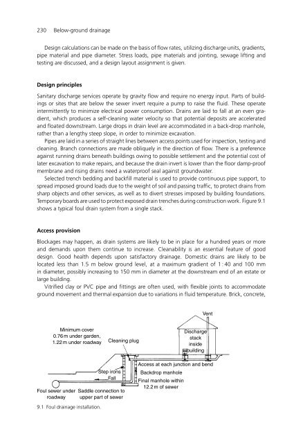
- Page 253 and 254: 232 Below-ground drainage Manhole:
- Page 255 and 256: 234 Below-ground drainage From Fig.
- Page 257 and 258: 236 Below-ground drainage storage v
- Page 259 and 260: 238 Below-ground drainage 14. The f
- Page 261 and 262: 240 Condensation in buildings mould
- Page 263 and 264: 242 Condensation in buildings The w
- Page 265 and 266: 244 Condensation in buildings EXAMP
- Page 267 and 268: 246 Condensation in buildings This
- Page 269 and 270: 248 Condensation in buildings Tempe
- Page 271 and 272: 250 Condensation in buildings and,
- Page 273 and 274: 252 Condensation in buildings EXAMP
- Page 275 and 276: 254 Condensation in buildings Tempe
- Page 277 and 278: 256 Condensation in buildings For t
- Page 279 and 280: 258 Condensation in buildings 4. Ev
- Page 281 and 282: 11 Lighting Learning objectives Stu
- Page 283 and 284: 262 Lighting Table 11.1 Typical val
- Page 285 and 286: 264 Lighting Light sources 9 9 9 Wi
- Page 287 and 288: 266 Lighting Utilization factor The
- Page 289 and 290: 268 Lighting From Table 11.3, for a
- Page 291 and 292: 270 Lighting Table 11.4 Lamp data.
- Page 293 and 294: 272 Lighting number of lamps = 12.8
- Page 295 and 296: 274 Lighting 3. Sketch and describe
- Page 297 and 298: 276 Lighting 4. Insufficient inform
- Page 299 and 300: 278 Lighting 3. 800 lm/m 2 . 4. 260
- Page 301 and 302:
12 Gas Learning objectives Study of
- Page 303 and 304:
282 Gas Open to atmosphere Rubber p
- Page 305 and 306:
284 Gas EL = (1.25 × 34) m = 42.5
- Page 307 and 308:
286 Gas become exhausted. SNG will
- Page 309 and 310:
288 Gas are ignited and an air flow
- Page 311 and 312:
290 Gas 3. The pipe from a gas mete
- Page 313 and 314:
292 Electrical installations Key te
- Page 315 and 316:
294 Electrical installations curren
- Page 317 and 318:
296 Electrical installations 1 Volt
- Page 319 and 320:
298 Electrical installations power
- Page 321 and 322:
300 Electrical installations For1mm
- Page 323 and 324:
302 Electrical installations Table
- Page 325 and 326:
304 Electrical installations Incomi
- Page 327 and 328:
306 Electrical installations energi
- Page 329 and 330:
308 Electrical installations Starte
- Page 331 and 332:
310 Electrical installations Ethyle
- Page 333 and 334:
312 Electrical installations Test o
- Page 335 and 336:
314 Electrical installations Joint
- Page 337 and 338:
316 Electrical installations 4. 100
- Page 339 and 340:
318 Electrical installations 39. Wh
- Page 341 and 342:
320 Electrical installations 51. Wh
- Page 343 and 344:
322 Room acoustics 20. understand t
- Page 345 and 346:
324 Room acoustics pump blades and
- Page 347 and 348:
326 Room acoustics ceiling, Q is 4.
- Page 349 and 350:
328 Room acoustics Table 14.2 Solut
- Page 351 and 352:
330 Room acoustics Table 14.3 Fan s
- Page 353 and 354:
332 Room acoustics Table 14.4 Illus
- Page 355 and 356:
334 Room acoustics (Sound Research
- Page 357 and 358:
336 Room acoustics The target room
- Page 359 and 360:
338 Room acoustics Table 14.6 Noise
- Page 361 and 362:
340 Room acoustics 100 90 80 70 Sou
- Page 363 and 364:
342 Room acoustics 24. A forced-dra
- Page 365 and 366:
344 Room acoustics The room directi
- Page 367 and 368:
346 Room acoustics 3. Multiple sour
- Page 369 and 370:
348 Room acoustics 55. Which is not
- Page 371 and 372:
350 Fire protection computer monito
- Page 373 and 374:
352 Fire protection halogen gas, wh
- Page 375 and 376:
354 Fire protection the reach of tu
- Page 377 and 378:
356 Fire protection Range pipe Spri
- Page 379 and 380:
358 Fire protection Fire compartmen
- Page 381 and 382:
360 Fire protection 16. Which are c
- Page 383 and 384:
362 Plant and service areas Key ter
- Page 385 and 386:
364 Plant and service areas 2.0 1.5
- Page 387 and 388:
366 Plant and service areas Fuel st
- Page 389 and 390:
368 Plant and service areas a minim
- Page 391 and 392:
370 Plant and service areas An unde
- Page 393 and 394:
372 Plant and service areas Air cha
- Page 395 and 396:
374 Plant and service areas 100 mm
- Page 397 and 398:
376 Plant and service areas Fire co
- Page 399 and 400:
378 Plant and service areas Table 1
- Page 401 and 402:
380 Plant and service areas 11. Wha
- Page 403 and 404:
17 Mechanical transportation Learni
- Page 405 and 406:
384 Mechanical transportation Table
- Page 407 and 408:
386 Mechanical transportation Crowd
- Page 409 and 410:
388 Mechanical transportation Hydra
- Page 411 and 412:
390 Mechanical transportation 4. Co
- Page 413 and 414:
18 Question bank Learning objective
- Page 415 and 416:
394 Question bank 8. Which correctl
- Page 417 and 418:
396 Question bank 5. This building
- Page 419 and 420:
398 Understanding units Questions 1
- Page 421 and 422:
400 Understanding units 15. Which i
- Page 423 and 424:
402 Understanding units 29. Which o
- Page 425 and 426:
404 Understanding units 43. Which i
- Page 427 and 428:
Appendix: answers to questions Chap
- Page 429 and 430:
408 Appendix Chapter 3 Heat loss ca
- Page 431 and 432:
410 Appendix 4. 0.007469 kg H 2 O/k
- Page 433 and 434:
412 Appendix 32. 5 33. 5 34. 3 35.
- Page 435 and 436:
414 Appendix 23. Lighting 1200 h/ye
- Page 437 and 438:
416 Appendix 27. 37 dB. 28. 39 dB.
- Page 439 and 440:
418 Appendix 15. 5 16. 2 17. 5 18.
- Page 441 and 442:
References Action Energy, Departmen
- Page 443 and 444:
Index Absorption 154, 324 Absorptio
- Page 445 and 446:
424 Index Gas burner controls 289 G
- Page 447 and 448:
426 Index Sensible heat gains 137 S