
Create successful ePaper yourself
Turn your PDF publications into a flip-book with our unique Google optimized e-Paper software.
Pfeiffer <strong>Vacuum</strong><br />
Formula 1-25<br />
Desorption from<br />
plastic material<br />
Formula 1-26<br />
Permeation<br />
Formula 1-27<br />
Leakage rate<br />
Formula 1-28<br />
Ultimate pressure (t)<br />
Page 24<br />
<strong>Vacuum</strong> <strong>Technology</strong><br />
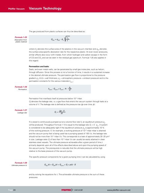
The gas produced from plastic surfaces can thus be described as:<br />
Q diff = q diff . Ad<br />
where A d denotes the surface area of the plastics in the vacuum chamber and q diff denotes<br />
the surface area-specific desorption rate for the respective plastic. At even lower pressures,<br />
similar effects also occur with metals, from which hydrogen and carbon escape in the form<br />
of CO and CO and can be seen in the residual gas spectrum. Formula 1-25 also applies in<br />
2<br />
this regard.<br />
Permeation and leaks<br />
Seals, and even metal walls, can be penetrated by small gas molecules, such as helium,<br />
through diffusion. Since this process is not a function of time, it results in a sustained increase<br />
in the desired ultimate pressure. The permeation gas flow is proportional to the pressure<br />
gradient p / d (d = wall thickness, p = atmospheric pressure = ambient pressure) and to the<br />
0 0<br />
permeation constants for the various materials k . perm<br />
k perm . Qperm = k perm . A .<br />
Permeation first manifests itself at pressures below 10 - 8 mbar.<br />
Q denotes the leakage rate, i.e. a gas flow that enters the vacuum system through leaks at a<br />
l<br />
volume of V. The leakage rate is defined as the pressure rise �p over time �t :<br />
�p . V<br />
Q = l �t<br />
If a vessel is continuously pumped out at a volume flow rate S, an equilibrium pressure pgl will be produced. Throughput Formula 1-13 is equal to the leakage rate Q = S l . p . A system<br />
g l<br />
is considered to be adequately tight if the equilibrium pressure p is approximately 10 %<br />
gl<br />
of the working pressure. If, for example, a working pressure of 10 - 6 mbar mbar is attained<br />
and the vacuum pump that is being used has a pumping speed of 100 l / s, the leakage rate<br />
should not be more than 10 - 5 mbar l / s. This corresponds to a leak of approximately 20 . 20 μm²<br />
in size. Leakage rates Q l of less than 10 - 8 mbar l / s can usually be easily attained in clean<br />
stainless steel vessels. The ultimate pressure achievable after a given period of time t<br />
primarily depends upon all of the effects described above and upon the pumping speed of<br />
the vacuum pump. The prerequisite is naturally that the ultimate pressure will be high<br />
relative to the base pressure of the vacuum pump.<br />
The specific pressure components for a given pumping time t can be calculated by using<br />
and by solving the equations for t. The achievable ultimate pressure is the sum of these<br />
pressures.<br />
t 0<br />
t<br />
p 0<br />
Q des (t) + Q diff (t) + Q perm + Q l = p(t) . S<br />
d<br />
www.pfeiffer-vacuum.net