
You also want an ePaper? Increase the reach of your titles
YUMPU automatically turns print PDFs into web optimized ePapers that Google loves.
Pfeiffer <strong>Vacuum</strong><br />
Page 40<br />
<strong>Vacuum</strong> <strong>Technology</strong><br />
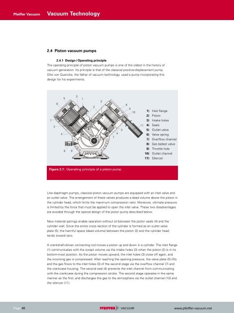
2.4 Piston vacuum pumps<br />
2.4.1 Design / Operating principle<br />
The operating principle of piston vacuum pumps is one of the oldest in the history of<br />
vacuum generation. Its principle is that of the classical positive-displacement pump.<br />
Otto von Guericke, the father of vacuum technology, used a pump incorporating this<br />
design for his experiments.<br />
7<br />
3<br />
6<br />
4<br />
5<br />
8 9<br />
3<br />
1<br />
Figure 2.7: Operating principle of a piston pump<br />
2<br />
3<br />
1) Inlet flange<br />
2) Piston<br />
3) Intake holes<br />
11 4) Seals<br />
5) Outlet valve<br />
6) Valve spring<br />
7) Overflow channel<br />
8) Gas ballast valve<br />
9) Throttle hole<br />
10) Outlet channel<br />
11) Silencer<br />
Like diaphragm pumps, classical piston vacuum pumps are equipped with an inlet valve and<br />
an outlet valve. The arrangement of these valves produces a dead volume above the piston in<br />
the cylinder head, which limits the maximum compression ratio. Moreover, ultimate pressure<br />
is limited by the force that must be applied to open the inlet valve. These two disadvantages<br />
are avoided through the special design of the piston pump described below.<br />
New material pairings enable operation without oil between the piston seals (4) and the<br />
cylinder wall. Since the entire cross section of the cylinder is formed as an outlet valve<br />
plate (5), the harmful space (dead volume) between the piston (2) and the cylinder head<br />
tends toward zero.<br />
A crankshaft-driven connecting rod moves a piston up and down in a cylinder. The inlet flange<br />
(1) communicates with the swept volume via the intake holes (3) when the piston (2) is in its<br />
bottom-most position. As the piston moves upward, the inlet holes (3) close off again, and<br />
the incoming gas is compressed. After reaching the opening pressure, the valve plate (5) lifts<br />
and the gas flows to the inlet holes (3) of the second stage via the overflow channel (7) and<br />
the crankcase housing. The second seal (4) prevents the inlet channel from communicating<br />
with the crankcase during the compression stroke. The second stage operates in the same<br />
manner as the first, and discharges the gas to the atmosphere via the outlet channel (10) and<br />
the silencer (11).<br />
7<br />
4<br />
3<br />
6<br />
5<br />
10<br />
www.pfeiffer-vacuum.net