manuale per l'installatore - 1/3 tipologie d'installazione - 2/3 software ...
manuale per l'installatore - 1/3 tipologie d'installazione - 2/3 software ...
manuale per l'installatore - 1/3 tipologie d'installazione - 2/3 software ...

Create successful ePaper yourself
Turn your PDF publications into a flip-book with our unique Google optimized e-Paper software.
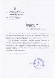
moving to the right. On the contrary,<br />
in each column the MAP<br />
value does not change while rpm<br />
increase moving down.<br />
Please keep in mind the MAP<br />
value increases (on the same rpm)<br />
according the throttle valve opening<br />
to (that is pressing the accelerator<br />
more); therefore during the<br />
self-mapping we move to the right<br />
on the map by accelerating, shifting<br />
up and looking for hill trial<br />
courses.<br />
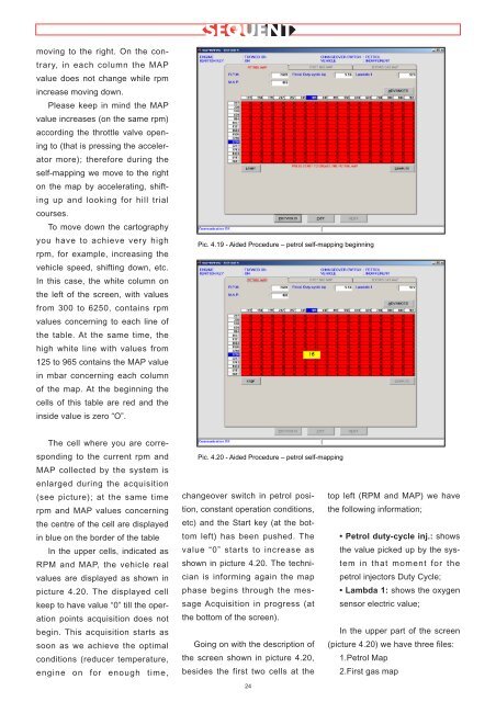
To move down the cartography<br />
you have to achieve very high<br />
rpm, for example, increasing the<br />
vehicle speed, shifting down, etc.<br />
In this case, the white column on<br />
the left of the screen, with values<br />
from 300 to 6250, contains rpm<br />
values concerning to each line of<br />
the table. At the same time, the<br />
high white line with values from<br />
125 to 965 contains the MAP value<br />
in mbar concerning each column<br />
of the map. At the beginning the<br />
cells of this table are red and the<br />
inside value is zero “O”.<br />
The cell where you are corresponding<br />
to the current rpm and<br />
MAP collected by the system is<br />
enlarged during the acquisition<br />
(see picture); at the same time<br />
rpm and MAP values concerning<br />
the centre of the cell are displayed<br />
in blue on the border of the table<br />
In the up<strong>per</strong> cells, indicated as<br />
RPM and MAP, the vehicle real<br />
values are displayed as shown in<br />
picture 4.20. The displayed cell<br />
keep to have value “0” till the o<strong>per</strong>ation<br />
points acquisition does not<br />
begin. This acquisition starts as<br />
soon as we achieve the optimal<br />
conditions (reducer tem<strong>per</strong>ature,<br />
engine on for enough time,<br />
Pic. 4.19 - Aided Procedure – petrol self-mapping beginning<br />
Pic. 4.20 - Aided Procedure – petrol self-mapping<br />
changeover switch in petrol position,<br />
constant o<strong>per</strong>ation conditions,<br />
etc) and the Start key (at the bottom<br />
left) has been pushed. The<br />
value “0” starts to increase as<br />
shown in picture 4.20. The technician<br />
is informing again the map<br />
phase begins through the message<br />
Acquisition in progress (at<br />
the bottom of the screen).<br />
Going on with the description of<br />
the screen shown in picture 4.20,<br />
besides the first two cells at the<br />
24<br />
top left (RPM and MAP) we have<br />
the following information;<br />
• Petrol duty-cycle inj.: shows<br />
the value picked up by the system<br />
in that moment for the<br />
petrol injectors Duty Cycle;<br />
• Lambda 1: shows the oxygen<br />
sensor electric value;<br />
In the up<strong>per</strong> part of the screen<br />
(picture 4.20) we have three files:<br />
1.Petrol Map<br />
2.First gas map