

LIBRARY ı6ıul 0) - Cranfield University
LIBRARY ı6ıul 0) - Cranfield University
LIBRARY ı6ıul 0) - Cranfield University

You also want an ePaper? Increase the reach of your titles
YUMPU automatically turns print PDFs into web optimized ePapers that Google loves.
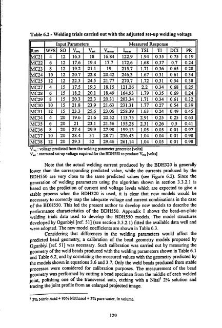
Table 6.2 - Welding trials carried out with the adjusted set-up welding voltage<br />
Input Parameters Measured Response<br />
Run WFS SO V V1 Vm, Imp TSI TI DCI PR<br />
-<br />
C21 4 12 16.3 18 16.84 122.9 1.94 0.35 0.75 0.19<br />
C22 6 12 17.6 19.4 17.7 172.6 1.68 0.37 0.7 0.24<br />
C23 8 12 19.2 21.1 19 215.7 1.71 0.36 0.65 0.28<br />
C24 10 12 20.7 22.8 20.42 246.3 1.67 0.31 0.61 0.34<br />
C25 12 12 22.3 24.5 21.77 270.7 1.72 0.31 0.54 0.38<br />
C27 4 15 17.5 19.3 18.15 121.26 2.2 0.34 0.68 0.25<br />
C28 6 15 18.2 20.1 18.49 164.93 1.79 0.35 0.69 0.24<br />
C29 8 15 20.3 22.3 20.31 203.34 1.71 0.34 0.61 0.32<br />
C30 10 15 21.8 23.9 21.63 231.31 1.77 0.27 0.54 0.39<br />
C31 12 15 23.3 25.6 23.06 258.39 1.63 0.24 0.49 0.45<br />
C34 4 20 19.6 21.6 20.52 113.75 2.91 0.25 0.25 0.63<br />
C35 6 20 21 23.1 21.56 155.28 2.31 0.26 0.5 0.41<br />
C36 8 20 27.4 29.9 27.98 199.13 1.05 0.05 0.01 0.97<br />
C37 10 20 28.4 31 28.71 236.43 1.04 0.04 0.01 0.98<br />
C38 12 20 29.3 32 29.46 261.14 1.04 0.05 0.01 0.98<br />
V, q: voltage predicted from the welding parameter generator [volts]<br />
V,, : corrected set-up voltage required for the BDH550 to produce V,,, q [volts]<br />
Note that the actual welding current produced by the BDH320 is generally<br />
lower than the corresponding predicted value, while the currents produced by the<br />
BDH550 are very close to the same predicted values (see Figure 6.2). Since the<br />
generation of welding parameters using the algorithm shown in section 3.3.2.1 is<br />
based on the prediction of current and voltage levels which are expected to give a<br />
stable process when the BDH320 is used, it is clear that new models would be<br />
necessary to correctly map the adequate voltage and current combinations in the case<br />
of the BDH550. This led the present author to develop new models to describe the<br />
performance characteristics of the BDH550. Appendix I shows the bead-on-plate<br />
welding trials data used to develop the BDH550 models. The model structures<br />
developed by Ogunbiyi [ref. 51 ] (see section 3.3.2.1) fitted the available data well and<br />
were adopted. The new model coefficients are shown in Table 6.3.<br />
Considering that differences in the welding parameters would affect the<br />
predicted bead geometry, a calibration of the bead geometry models proposed by<br />
Ogunbiyi [ref 51] was necessary. Such calibration was carried out by measuring the<br />
geometry of the weld beads produced with the welding parameters shown in Table 6.1<br />
and Table 6.2, and by correlating the measured values with the geometry predicted by<br />
the models shown in equations 3.6 and 3.7. Only the weld beads produced from stable<br />
processes were considered for calibration purposes. The measurement of the bead<br />
geometry was performed by cutting a bead specimen from the middle of each welded<br />
joint, polishing one of the transversal cuts, etching with a Nital' 2% solution and<br />
tracing the joint profile from an enlarged projected image.<br />
1 2% Nitric Acid + 95% Methanol + 3% pure water, in volume.<br />
129


