

LIBRARY ı6ıul 0) - Cranfield University
LIBRARY ı6ıul 0) - Cranfield University
LIBRARY ı6ıul 0) - Cranfield University

You also want an ePaper? Increase the reach of your titles
YUMPU automatically turns print PDFs into web optimized ePapers that Google loves.
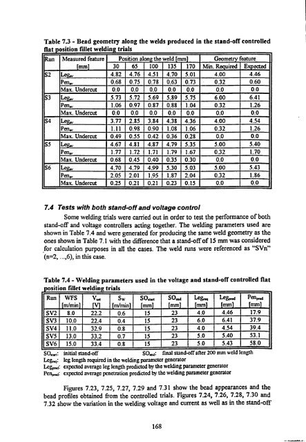
Table 7.3 - Bead geometry along the welds produced in the stand-off controlled<br />
flat position fillet welding trials<br />
Run Measured feature Position aloe the weld mm Geometry feature<br />
mm 30 65 100 135 170 Min. Required Expected<br />
S2 Le 4.82 4.76 4.51 4.70 5.01 4.00 4.46<br />
Pen, 0.68 0.75 0.78 0.63 0.73 0.32 0.60<br />
Max. Undercut 0.0 0.0 0.0 0.0 0.0 0.0 0.0<br />
S3 Le 5.73 5.72 5.69 5.89 5.75 6.00 6.41<br />
Pence. 1.06 0.97 0.87 0.88 1.04 0.32 1.26<br />
Max. Undercut 0.0 0.0 0.0 0.0 0.0 0.0 0.0<br />
S4 Le 3.77 2.85 3.84 4.38 4.36 4.00 4.54<br />
Pen,,, 1.11 0.98 0.90 1.08 1.06 0.32 1.26<br />
Max. Undercut 0.49 0.55 0.42 0.36 0.28 0.0 0.0<br />
S5 4.67 4.81 4.87 4.79 5.35 5.00 5.40<br />
Pen,,. 1.77 1.72 1.71 1.79 1.67 0.32 1.70<br />
Max. Undercut 0.68 0.45 0.40 0.35 0.30 0.0 0.0<br />
S6 Le 4.70 4.79 4.99 5.30 5.03 5.00 5.43<br />
Pen,,. 2.05 2.01 1.95 1.87 2.04 0.32 1.86<br />
Max. Undercut 0.25 0.21 0.21 0.23 0.15 0.0 0.0<br />
7.4 Tests with both stand-off and voltage control<br />
Some welding trials were carried out in order to test the performance of both<br />
stand-off and voltage controllers acting together. The welding parameters used are<br />
shown in Table 7.4 and were generated for producing the same weld geometry as the<br />
ones shown in Table 7.1 with the difference that a stand-off of 15 mm was considered<br />
for calculation purposes in all the cases. The weld runs were referenced as "SVn"<br />
(n=2,..., 6), in this case.<br />
Table 7.4 - Welding parameters used in the voltage and stand-off controlled flat<br />
position fillet welding trials<br />
Run WFS<br />
m/min<br />
V,., Sw<br />
minim<br />
SO,, rt<br />
mm<br />
SOme<br />
mm<br />
Leg,. q<br />
mm<br />
Legp,. a<br />
mm<br />
Pen..<br />
[mm]<br />
SV2 8.0 22.2 0.6 15 23 4.0 4.46 17.9<br />
SV3 10.0 22.4 0.4 15 23 6.0 6.41 37.9<br />
SV4 11.0 32.9 0.8 15 23 4.0 4.54 39.4<br />
SV5 13.0 33.2 0.7 15 23 5.0 5.40 53.1<br />
SV6 15.0 33.4 0.8 15 23 5.0 5.43 58.0<br />
SO.,,: initial stand-off SO, e:<br />
final stand-off after 200 mm weld length<br />
Leg,. leg length<br />
q: required in the welding parameter generator<br />
Legj: expected average leg length predicted by the welding parameter generator<br />
Pence: expected average penetration predicted by the welding parameter generator<br />
Figures 7.23,7.25,7.27,7.29 and 7.31 show the bead appearances and the<br />
bead profiles obtained from the controlled trials. Figures 7.24,7.26,7.28,7.30 and<br />
7.32 show the variation in the welding voltage and current as well as in the stand-off<br />
168


