

LIBRARY ı6ıul 0) - Cranfield University
LIBRARY ı6ıul 0) - Cranfield University
LIBRARY ı6ıul 0) - Cranfield University

Create successful ePaper yourself
Turn your PDF publications into a flip-book with our unique Google optimized e-Paper software.
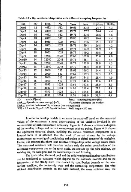
Table 6.7 - Dip resistance dispersion with different sampling frequencies<br />
Run SO Freq. Nw V.. I. Di R. Di RSD<br />
Di rl 12 4032 512 19.61 163.5 24.7 4.3<br />
Di r2 14 4032 512 19.71 157.2 26.6 4.4<br />
Di r3 16 4032 512 19.71 153.6 28.6 4.6<br />
Di r4 18 4032 512 19.80 148.2 30.6 4.4<br />
Di r5 12 8065 1024 19.60 164.6 25.1 4.2<br />
Di r6 14 8065 1024 19.71 159.1 26.8 4.2<br />
Di r7 16 8065 1024 19.71 154.2 28.9 4.3<br />
Di r8 18 8065 1024 19.77 149.2 30.8 4.6<br />
Di r9 12 12500 2048 19.66 162.0 25.0 4.0<br />
Di r10 14 12500 2048 19.73 158.1 27.1 4.4<br />
Di rl1 16 12500 2048 19.75 151.9 28.9 4.5<br />
Di r12 18 12500 2048 19.76 148.4 31.0 4.7<br />
Diprl3 12 2000 512 19.62 166.2 24.4 4.5<br />
Di rl4 14 2000 512 19.69 159.3 27.3 4.5<br />
Di r15 16 2000 512 19.69 154.8 28.4 4.0<br />
Di r16 18 2000 512 19.78 148.6 30.6 4.2<br />
Di r17 12 4032 1024 19.61 167.8 25.0 5.3<br />
Di r18 14 4032 1024 19.61 159.4 27.1 4.4<br />
Di r19 16 4032 1024 19.71 154.5 28.8 4.3<br />
Di r20 18 4032 1024 19.76 148.0 31.0 4.4<br />
SO: stand-off [mm], Freq.: sampling frequency [Hz]<br />
DipR,,.,,: dip resistance (run average) [nL ], Nw: number of samples in a window<br />
DipRsD: standard deviation of dip resistance (run average) [mS)]<br />
WFS = 6.0 m/min, V, d = 21.5 V, Sw = 0.5 m/min, Weld length = 200 mm<br />
In order to develop models to estimate the stand-off based on the measured<br />
values of dip resistance, a good understanding of the variables involved in the<br />
measurement of such resistance is necessary. Figure 6.13 shows a schematic diagram<br />
of the welding voltage and current measurement pick-up points. Figure 6.14 shows<br />
the equivalent electrical circuit, outlining the various resistance components in a<br />
lumped form. It is assumed that the level of current drained by the voltage<br />
measurement system (signal conditioning and analog to digital converter) is negligible.<br />
Hence, it is assumed that there is no resistive voltage drop in the voltage sensor leads.<br />
The measured resistance will therefore include only the series combination of the<br />
resistance components due to the torch cable, the contact tip, the wire stickout, the<br />
welding arc, the weld pool and the solid workpiece and fixturing.<br />
The torch cable, the weld pool and the solid workpiece/fixturing contributions<br />
can be considered as constants which depend on the materials involved and on the<br />
temperature in the steady state. The contact tip contribution depends on the wire<br />
surface condition, the contact-tip wear and the contact-tip temperature. The wire<br />
stickout contribution depends on the wire material, the cross sectional area, the<br />
137


